 |
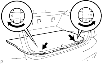
Unlock the 2 washer tank cover knobs, and then remove the rear floor board.
CYLINDER HEAD > REMOVAL |
| 1. DISCHARGE FUEL SYSTEM PRESSURE |
Remove the integration relay (unit C: C/OPN relay) from the engine room junction block.
Start the engine. After the engine has stopped, turn the power switch off.
Check that the engine does not start.
Remove the fuel tank cap, and let the air out of the fuel tank.
Disconnect the cable from the negative (-) battery terminal.
Install the integration relay (unit C: C/OPN relay) to the engine room junction block.
| 2. PRECAUTION |
| 3. REMOVE REAR NO. 2 FLOOR BOARD |
|
Unlock the 2 washer tank cover knobs, and then remove the rear floor board.
| 4. REMOVE REAR DECK FLOOR BOX |
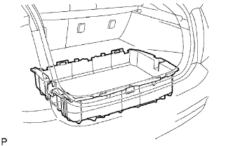 |
Remove the rear deck floor box from the vehicle.
| 5. REMOVE REAR NO. 3 FLOOR BOARD |
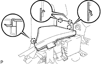 |
Detach the 4 claws, and then remove the floor board.
| 6. DISCONNECT CABLE FROM NEGATIVE BATTERY TERMINAL |
| 7. REMOVE SERVICE PLUG GRIP |
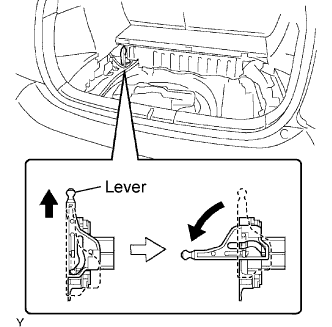 |
Slide up the lever of the service plug grip. Remove the service plug grip while turning the lever to the left.
Insulate the service plug with insulating tape.
| 8. DISCONNECT FRONT EXHAUST PIPE ASSEMBLY |
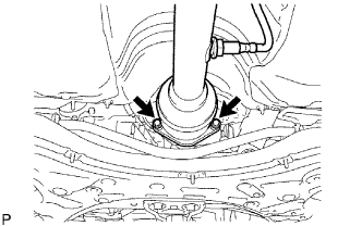 |
Remove the 2 bolts and 2 compression rings, then disconnect the exhaust pipe assembly front from the exhaust manifold.
| 9. REMOVE INVERTER WITH CONVERTER ASSEMBLY |
Remove the inverter with converter from the vehicle (Click here).
| 10. REMOVE CHAIN |
Remove the chain from the engine (Click here).
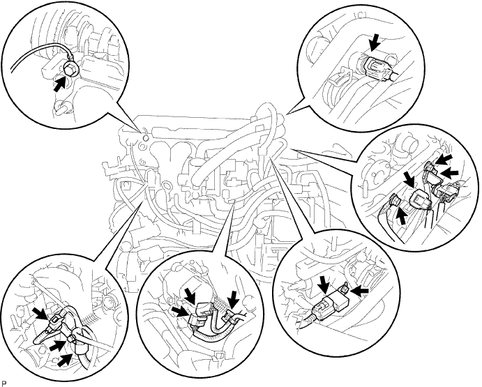
| 11. DISCONNECT WIRE HARNESS |
Disconnect the connectors and wire harnesses shown in the illustration.
| 12. REMOVE FUEL MAIN TUBE |
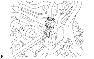 |
Remove the fuel pipe clamp.
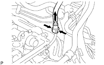 |
Disconnect the fuel tube from the fuel delivery pipe.
Cover the disconnected fuel tube and fuel delivery pipe with a plastic bag in order to prevent foreign objects from entering them.
| 13. DISCONNECT RADIATOR INLET HOSE |
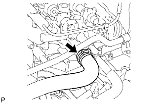 |
Disconnect the radiator inlet hose from the cylinder head.
| 14. DISCONNECT HOSES |
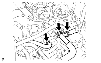 |
Disconnect the hoses from the cylinder head as shown in the illustration.
| 15. DISCONNECT NO. 1 WATER BY-PASS PIPE |
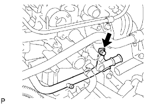 |
Remove the bolt and disconnect the water by-pass pipe.
| 16. REMOVE OIL DIPSTICK GUIDE |
Disconnect the hoses shown in the illustration.
Remove the bolt and disconnect the dipstick guide.
| 17. REMOVE CYLINDER HEAD |
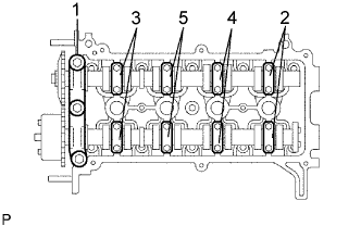 |
Remove the No. 1 and No. 2 camshaft bearing caps in the sequence shown in the illustration, then remove the camshaft and No. 2 camshaft.
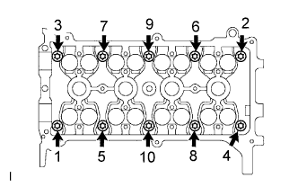 |
Using an 8 mm bi-hexagon wrench, loosen the cylinder head bolts in several steps in the sequence shown in the illustration. Then remove the cylinder head bolts and washer.
Remove the cylinder head.
| 18. REMOVE CYLINDER HEAD GASKET |
| 19. REMOVE INTAKE MANIFOLD |
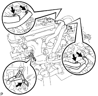 |
Remove the bolt and knock control sensor with bracket.
Disconnect the wiring harness from the bracket.
Disconnect the ventilation hose.
Disconnect the water by-pass hose.
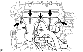 |
Remove the 3 bolts and 2 nuts, then remove the intake manifold and gasket.
| 20. REMOVE EXHAUST MANIFOLD |
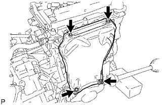 |
Remove the 4 bolts and exhaust manifold insulator.
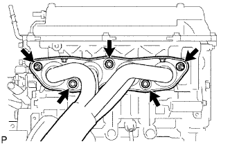 |
Remove the 3 bolts and 2 nuts, then remove the exhaust manifold.
| 21. REMOVE NOISE FILTER |
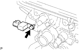 |
Remove the bolt and noise filter.
| 22. REMOVE ENGINE COOLANT TEMPERATURE SENSOR |
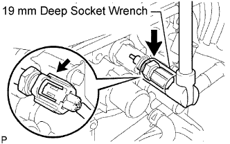 |
Disconnect the sensor connector.
Using a 19 mm deep socket wrench, remove the sensor and gasket.
| 23. REMOVE FUEL DELIVERY PIPE |
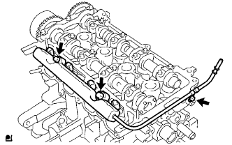 |
Remove the 3 bolts and fuel delivery pipe together with the 4 fuel injectors.
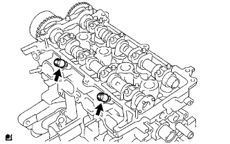 |
Remove the delivery pipe spacer from the cylinder head.
| 24. REMOVE FUEL INJECTOR |
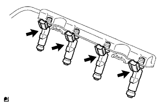 |
Pull out the 4 injectors from the delivery pipe.