TIMING CHAIN > INSTALLATION |
| 1. INSTALL CHAIN |
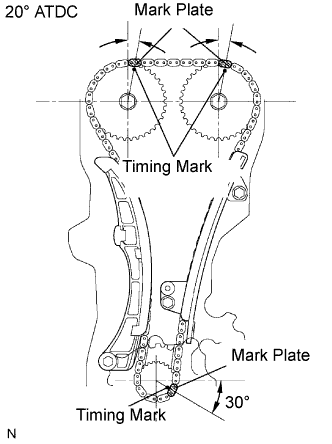
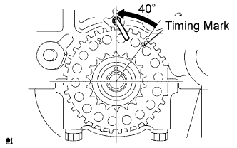
Set the position of the No. 1 cylinder to 20° ATDC.
![]() |
Set the crankshaft between 40 to 140° ATDC.
Set the cams of the intake and exhaust timing sprockets to 20° ATDC.
Reset the crankshaft to 20° ATDC.
Install the chain vibration damper with the 2 bolts.
![]() |
Align the timing marks of the camshaft timing sprocket, camshaft timing gear and crankshaft timing sprocket with each mark plate (colored in yellow) of the timing chain.
![]() |
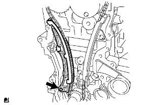
Install the chain tensioner slipper with the bolt.
![]() |
Install the chain tensioner with the 2 bolts.
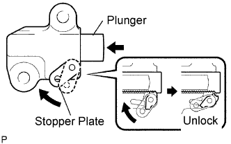
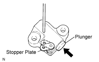
Lift up the stopper plate, then unlock the plunger.
Push in the plunger to the end with the plunger unlocked.
![]() |
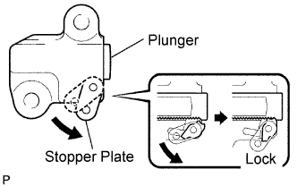
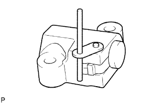
Lower the stopper plate with the plunger pushed to the end, then lock the plunger.
![]() |
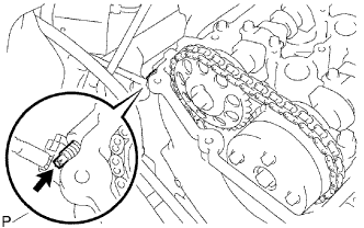
Insert a 3.0 mm (0.118 in.) diameter bar into the hole of the stopper plate with the plunger locked.
![]() |
![]() |
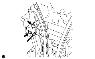
Install the chain tensioner with the 2 bolts.
Remove the bar from the chain tensioner.
Check the tension between the intake and exhaust camshaft timing sprockets.
| 2. INSTALL OIL PUMP SEAL |
![]() |
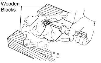
Using a screwdriver with its tip wrapped in tape, remove the oil seal.
![]() |
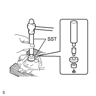
Using SST, uniformly tap in a new oil seal until its surface is flush with the oil pump edge.
Apply a light coat of No. 2 multipurpose grease to the lip of the oil seal.
| 3. INSTALL TIMING CHAIN COVER |
![]() |
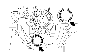
Install 2 new O-rings to the 2 locations as shown in the illustration.
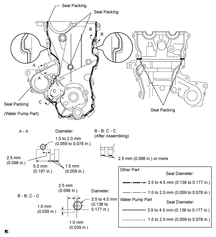
Apply seal packing to the engine body and oil pump as shown in the illustration below.

![]() |
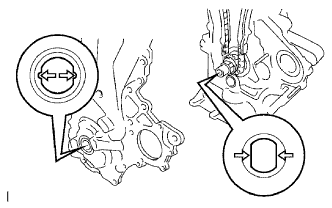
Align the drive rotor spline of the oil pump with the rectangular portion of the crankshaft, then slide the oil pump into place.
![]() |
Using an E8 "torx" socket wrench, install the stud bolt.
![]() |
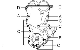
Install the oil pump with the 15 bolts and nut as illustrated.
| 4. INSTALL CRANKSHAFT POSITION SENSOR |
Install the sensor with the bolt.
Connect the sensor connector.
| 5. INSTALL CAMSHAFT TIMING OIL CONTROL VALVE ASSEMBLY |
![]() |
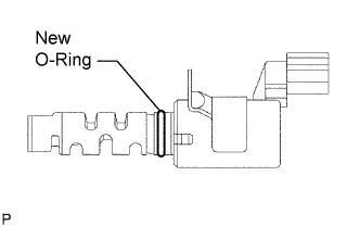
Apply a light coat of engine oil to a new O-ring, then install it to the camshaft timing oil control valve.
Install the camshaft timing oil control valve with the bolt.
Connect the camshaft timing oil control valve connector.
| 6. INSTALL ENGINE MOUNTING BRACKET |
![]() |
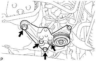
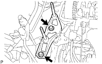
Install the engine mounting bracket with the 4 bolts.
| 7. INSTALL ENGINE MOUNTING SPACER |
![]() |
Install the engine mounting spacer with the 2 bolts.
| 8. INSTALL ENGINE MOUNTING INSULATOR RH |
![]() |
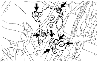
Install the engine mounting insulator RH with the 3 bolts and 4 nuts.
| 9. INSTALL CRANKSHAFT PULLEY |
![]() |
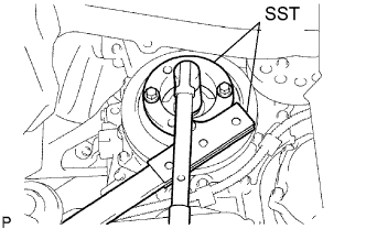
Align the hole of the crankshaft damper with the straight pin, then install the crankshaft damper.
Using SST, hold the crankshaft damper and tighten the crankshaft bolt.
| 10. INSTALL WATER PUMP |
![]() |
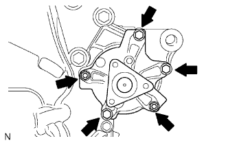
Install a new gasket and the water pump with the 3 bolts and 2 nuts.
| 11. INSTALL DRIVE BELT |
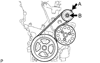
Temporarily install the belt on each pulley.
| 12. CHECK DRIVE BELT TENSION |
![]() |
Turn adjust bolt B to adjust the belt tension.
Tighten nut A.
| 13. INSTALL PURGE VSV |
![]() |
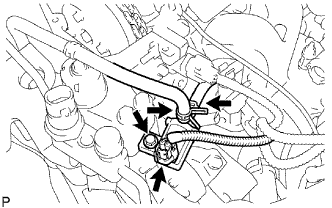
Install the purge VSV with the bolt.
Connect the hose and connector.
| 14. INSTALL CYLINDER HEAD COVER |
![]() |
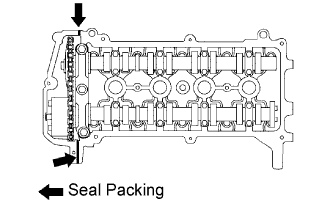
Apply seal packing to the 2 locations shown in the illustration, then install the cylinder head cover.
![]() |
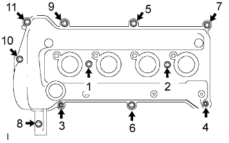
Install the cylinder head cover with the 9 bolts and 2 nuts.
Using several steps, tighten the bolts and nuts to the specified torque in the sequence shown in the illustration.
![]() |
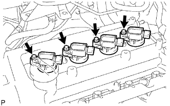
Install the ignition coil with the bolt.
![]() |
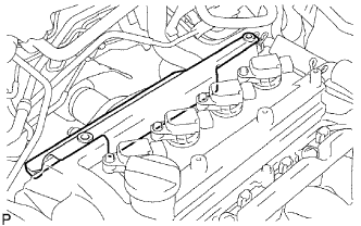
Install the brake master cylinder reservoir cover to the cylinder head cover.
![]() |
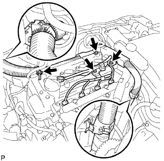
Install the wire harness and brake master cylinder reservoir cover with the 3 bolts.
Connect the fuel injector connector and ignition coil connector.
| 15. INSTALL WINDSHIELD WASHER JAR |
![]() |
Install the windshield washer with the 2 bolts and nut.
Connect the 2 connectors and wire harness.
| 16. INSTALL RESERVOIR BRACKET |
![]() |
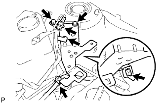
Install the reservoir bracket with the 3 bolts and connect the wire harness clamp.
| 17. INSTALL BRAKE MASTER CYLINDER RESERVOIR |
![]() |
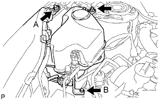
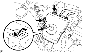
Attach the claw and install the master cylinder reservoir with the 2 bolts.
Connect the connector.
| 18. INSTALL NO. 2 AIR CLEANER INLET |
![]() |
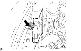
Install the air cleaner inlet with the clip.
| 19. INSTALL AIR CLEANER ASSEMBLY |
![]() |
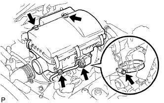
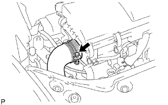
Install the air cleaner with the 2 bolts and tighten the clamp.
Connect the MAF meter connector and clamp.
![]() |
Connect the No. 1 air inlet, and then tighten the clamp.
| 20. INSTALL FRONT COWL TOP PANEL OUTER |
| 21. INSTALL WINDSHIELD WIPER MOTOR AND WIPER LINK ASSEMBLY |
![]() |
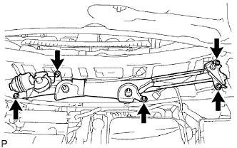
Install the windshield wiper motor & link with the 5 bolts.
Connect the connector.
| 22. INSTALL COWL TOP VENTILATOR LOUVER RH |
| 23. INSTALL COWL TOP VENTILATOR LOUVER LH |
| 24. INSTALL HOOD TO COWL TOP SEAL |
| 25. INSTALL FRONT WIPER ARM LH |
![]() |
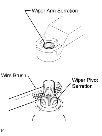
Clean the wiper arm serration with a round file or equivalent (when reinstalling).
Clean the wiper pivot serration with a wire brush.
![]() |
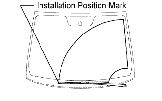
Install the front wiper arm LH with the nut so that the front wiper blade comes to the position shown in the illustration.
| 26. INSTALL FRONT WIPER ARM RH |
![]() |
Clean the wiper arm serration with a round file or equivalent (when reinstalling).
Clean the wiper pivot serration with a wire brush.
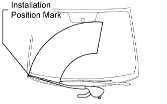
Install the front wiper arm RH with the 2 nuts so that the front wiper blade comes to the position shown in the illustration.
Operate the front wipers while spraying water or washer fluid on the windshield glass. Ensure that the wipers function properly and there is no interference with the body.
| 27. INSTALL WIPER ARM HEAD CAP |
| 28. ADD ENGINE OIL |
Add fresh engine oil and install the oil filler cap.
| Oil Grade | Oil Viscosity (SAE) |
| ILSAC multigrade engine oil |
|
| Item | Fill amount |
| Drain and refill with oil filter change | 3.7 liters (3.9 US qts, 3.3 Imp. qts) |
| Drain and refill without oil filter change | 3.4 liters (3.6 US qts, 3.0 Imp. qts) |
| Dry fill | 4.1 liters (4.3 US qts, 3.6 Imp. qts) |
| 29. CONNECT CABLE TO NEGATIVE BATTERY TERMINAL |
![]() |
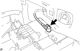
Connect the battery negative cable, and then tighten the nut.
| 30. INSTALL REAR NO. 3 FLOOR BOARD |
![]() |
Install the floor board, and then attach the 4 claws.
| 31. INSTALL REAR DECK FLOOR BOARD |
![]() |
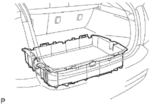
Install the rear deck floor box to the vehicle.
| 32. INSTALL REAR NO. 2 FLOOR BOARD |
![]() |
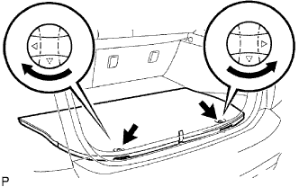
Install the floor board, and then lock the 2 cover knobs.
| 33. ADD ENGINE COOLANT |
Tighten the drain cock plug of the coolant heat storage tank, then disconnect the vinyl hose.
Tighten the drain cock plug of the engine, then disconnect the vinyl hose.
Tighten the drain cock plug of the radiator, then disconnect the vinyl hose.
![]() |
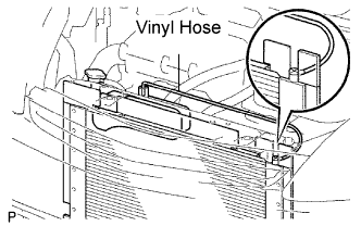
Connect a vinyl hose to the bleeder plug of the radiator assembly and the radiator reservoir.
![]() |
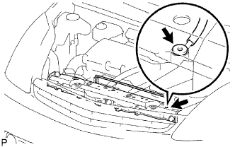
Using a 6 mm socket hexagon wrench, loosen the radiator bleeder plug from the radiator support service hole.
Fill the radiator with coolant up to the fill port.
Using a 6 mm socket hexagon wrench, tighten the radiator bleeder plug.
Install the radiator cop.
Fill the radiator reservoir tank with coolant to the full level.
Connect the coolant heat storage water pump connector.
Connect the Techstream to the DLC3.
Turn the power switch ON (IG).
Select the item:
Powertrain / Engine and ECT / Data List/Activate the Water Pump
![]() |
Using a 6 mm socket hexagon wrench, loosen the radiator bleeder plug from the radiator support service hole.
Remove the radiator cap, then fill the radiator with coolant up to the fill port.
Using a 6 mm socket hexagon wrench, tighten the radiator bleeder plug.
Install the radiator cap.
Slowly pour coolant into the radiator reservoir until it reaches the full line.
Disconnect the vinyl hose between the bleeder plug of the radiator assembly and the radiator reservoir tank.
Set the vehicle to inspection mode (Click here).
Warm up the engine until the thermostat is open.
Stop the engine, then wait until the coolant becomes cold. Remove the radiator cap and check the coolant level.
When the coolant level stops going down, add coolant to the radiator reservoir tank up to the full level.
| 34. INSPECT FOR ENGINE COOLANT LEAK |
![]() |
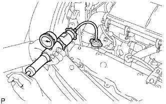
Fill the radiator with coolant and attach a radiator cap tester.
Warm up the engine.
Using the radiator cap tester, increase the pressure inside the radiator to 177 kPa (1.8 kgf/cm2, 25.6 psi), and check that the pressure does not drop.
If the pressure drops, check the hoses, radiator and water pump for leaks. If no external leaks are found, check the cylinder block and head.
| 35. INSTALL RADIATOR SUPPORT OPENING COVER |
| 36. INSTALL NO. 4 CENTER ENGINE UNDER COVER |
| 37. INSTALL NO. 3 ENGINE UNDER COVER |
| 38. INSTALL FRONT WHEELS |
| 39. PERFORM INITIALIZATION |
Perform initialization (Click here).