Home › ENGINE › 1NZ-FXE ENGINE CONTROL SYSTEM › SFI SYSTEM

DTC    P0325    Knock Sensor 1 Circuit

DTC    P0327    Knock Sensor 1 Circuit Low Input (Bank 1 or Single Sensor)

DTC    P0328    Knock Sensor 1 Circuit High Input (Bank 1 or Single Sensor)

for Preparation Click here


DESCRIPTION

A flat type knock sensor (non-resonant type) has the structure that can detect vibrations in a wider band of the frequency from about 6 kHz to 15 kHz and has the following features.
Knock sensors are fitted on the cylinder block to detect engine knocking.
The knock sensor contains a piezoelectric element which generates voltage when it becomes deformed. The generation of the voltage occurs when the cylinder block vibrates due to the knocking. If the engine knocking occurs, in order to suppress it, the ignition timing is retarded.

DTC No.
DTC Detection Condition
Trouble Area
P0325
Knock sensor signal level remains at low for 1 second
  1. Open or short in knock sensor circuit
  2. Knock sensor (under-torqued or looseness)
  3. ECM
P0327
Output voltage of the knock sensor is less than 0.5 V
  1. Short in knock sensor circuit
  2. Knock sensor
  3. ECM
P0328
Output voltage of the knock sensor is more than 4.5 V
  1. Open in knock sensor circuit
  2. Knock sensor
  3. ECM

HINT:
If the ECM detects DTC P0325,P0327 and P0328, it enters fail-safe mode in which the corrective retarded angle value is set to its maximum value.

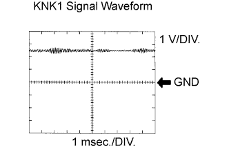
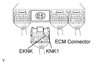
Reference: Inspection by using an oscilloscope.
A085286E44
(1) After warming up, run the engine at 2,500 rpm, and check and the waveform between terminals KNK1 and EKNK of the ECM connector.

MONITOR DESCRIPTION

The knock sensor, located on the cylinder block, detects engine knockings. When the engine knockings occur, the sensor detects vibrations in a specific frequency range. When the ECM detects the voltage in this frequency range, it retards the ignition timing to suppress the engine knockings.
The ECM also senses background engine noise with the knock sensor and uses this noise to check for faults in the sensor. If the knock sensor signal level is too low for more than 10 seconds, and if the knock sensor output voltage is out of the normal range, the ECM interprets this as a fault in the knock sensor and sets a DTC.

MONITOR STRATEGY


Related DTCs
P0325: Knock sensor (bank 1) range check or rationality
P0327: Knock sensor (bank 1) range check (low voltage)
P0328: Knock sensor (bank 1) range check (high voltage)
Required sensors/components (main)
Main:
Knock sensor
Related: Crankshaft position sensor,
camshaft position sensor, engine coolant temperature sensor, mass air flow meter
Frequency of operation
Continuous
Duration
1 second
MIL operation
Immediately
Sequence of operation
None

TYPICAL ENABLING CONDITIONS


The monitor will run whenever the following DTCs are not present
None
Battery voltage
10.5 V or more
Time after engine start
5 seconds or more

TYPICAL MALFUNCTION THRESHOLDS


Case 1: P0325 
Knock sensor voltage
Less than 0.5 V and more than 4.5 V

Case 2: P0327 
Knock sensor voltage
Less than 0.5 V

Case 3: P0328 
Knock sensor voltage
More than 4.5 V

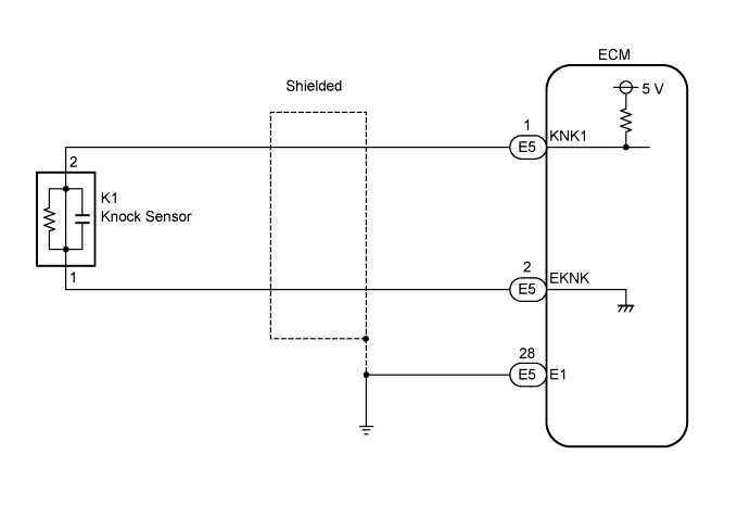
WIRING DIAGRAM


A151891E01


INSPECTION PROCEDURE

HINT:
Read freeze frame data using Techstream. The ECM records vehicle and driving condition information as freeze frame data the moment a DTC is stored. When troubleshooting, freeze frame data can be helpful in determining whether the vehicle was running or stopped, whether the engine was warmed up or not, whether the air/fuel ratio was lean or rich, as well as other data recorded at the time of a malfunction.

1.READ OUTPUT DTCS
  1. Connect Techstream to the DLC3.

  1. Turn the power switch ON (IG).

  1. Turn Techstream ON.

  1. Enter the following menus: Powertrain / Engine and ECT / Trouble Code.

  1. Clear the DTCs.

  1. Put the engine in inspection mode (Click here).

  1. Warm up the engine.

  1. Run the engine at 2,500 rpm for 10 seconds or more.

  1. Read the DTCs.

Result:
Display (DTC output)
Proceed to
P0325
A
P0325, P0327 and/or P0328
B
No output
C


B
Go to step 3

C
CHECK FOR INTERMITTENT PROBLEMS
A


2.INSPECT KNOCK SENSOR
  1. Check the knock sensor installation.

    OK:
    Torque: 20 N*m (204 kgf*cm, 15 ft.*lbf)


NG
SECURELY REINSTALL SENSOR
OK

REPLACE KNOCK SENSOR 

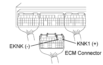
3.CHECK HARNESS AND CONNECTOR (ECM - KNOCK SENSOR)


    A065745E45
  1. Disconnect the E5 ECM connector.

  1. Measure the resistance between the terminals of the E5 ECM connector.

    Standard resistance:
    Tester Connection
    Specified Condition
    E5-1 (KNK1) - E5-2 (EKNK)
    120 to 280 kΩ at 20°C (68°F)

  1. Reconnect the ECM connector.


NG
Go to step 5
OK


4.INSPECT ECM (KNK1 - EKNK VOLTAGE)


    A084937E10
  1. Disconnect the E5 ECM connector.

  1. Turn the power switch ON (IG).

  1. Measure the voltage between the terminals of the E5 ECM terminals.

    Standard voltage:
    Tester Connection
    Specified Condition
    E5-1 (KNK1) - E5-2 (EKNK)
    4.5 to 5.5 V

  1. Reconnect the ECM connector


NG
REPLACE ECM
OK

CHECK FOR INTERMITTENT PROBLEMS 

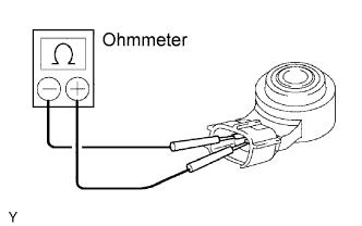
5.INSPECT KNOCK SENSOR


    A065174E11
  1. Remove the knock sensor.

  1. Measure the resistance between the terminals.

    Standard resistance:
    Tester Connection
    Specified Condition
    K1-2 (KNK1) - K1-1 (EKNK)
    120 to 280 kΩ at 20°C (68°F)

  1. Reinstall the knock sensor.


NG
REPLACE KNOCK SENSOR
OK

REPAIR OR REPLACE HARNESS OR CONNECTOR