| A |  |
| GO TO DIAGNOSTIC TROUBLE CODE CHART |
DTC P0A08-264 DC / DC Converter Status Circuit |
| DTC No. | INF Code | DTC Detection Condition | Trouble Area |
| P0A08 | 264 | All conditions below are detected
|
|
| 1.CHECK FOR DTC |
Clear the DTC(s) (Click here).
Connect the Techstream to the DLC3.
Turn the power switch ON (IG).
Read DTC(s).
| Result | Proceed to |
| One or more of following DTCs is output: P0A94, P0AA1, P0AA4, P0AA6, P0AE0, P0AE6, P0AE7, P0ADB, P0ADF, P3000, P3004, P3110 | A |
| P0A08 is output | B |
|
| ||||
| B | |
 |
| 2.CHECK CABLE CONNECTION FROM AUXILIARY BATTERY TERMINAL |
Turn the power switch OFF.
Check the auxiliary battery (12 V) cable connections at places listed below:
|
| ||||
| OK | |
|
| 3.CHECK CONNECTION OF CONNECTORS (FUSIBLE LINK BLOCK ASSEMBLY) |
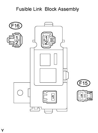 |
Check that the F15 and F16 connectors are securely connected to the fusible link block assembly.
|
| ||||
| NG | |
|
| 4.CHECK CONNECTOR (FUSIBLE LINK BLOCK ASSEMBLY) |
Check that the F15 and F16 connector terminals do not have burnout.
|
| ||||
| OK | |
|
| 5.INSPECT FUSIBLE LINK BLOCK ASSEMBLY |
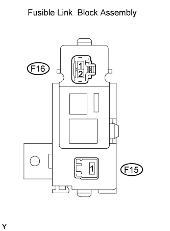 |
Measure the resistance between the F15 fusible link block assembly and body ground.
| Tester Connection | Specified Condition |
| F15-1 Body ground | Below 1 Ω |
Measure the resistance between the F16 fusible link block assembly and body ground.
| Tester Connection | Specified Condition |
| F16-1 - Body ground | Below 1 Ω |
| F16-2 - Body ground | Below 1 Ω |
|
| ||||
|
| ||||
| OK | |
|
| 6.CHECK INSTALLATION CONDITION OF DC / DC FUSE (ENGINE ROOM JUNCTION BLOCK) |
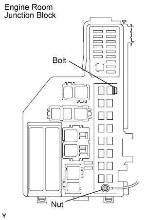 |
Check the installation condition of the DC / DC fuse.
|
| ||||
| OK | |
|
| 7.CHECK FUSIBLE LINK BLOCK ASSEMBLY (100A DC / DC-S) |
Remove the DC / DC-S fuse from the fusible link block assembly.
Measure the resistance of the fuse.
|
| ||||
| OK | |
|
| 8.CHECK CONNECTION OF CONNECTORS (HV CONTROL ECU) |
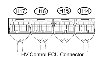 |
Check that the H14, H15, H16 and H17 ECU connectors are securely connected.
|
| ||||
| OK | |
|
| 9.CHECK CONNECTION OF CONNECTORS (INVERTER WITH CONVERTER ASSEMBLY) |
Turn the power switch OFF.
Remove the service plug grip (Click here).
Leave the vehicle as is for 5 minutes.
Remove the inverter cover .
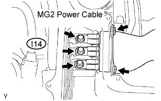 |
Remove the 5 bolts to disconnect the MG2 power cable.
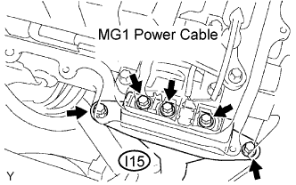 |
Remove the 5 bolts to disconnect the MG1 power cable.
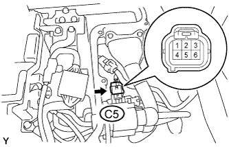 |
Check the connection condition of the C5 connector.
|
| ||||
| OK | |
|
| 10.CHECK CONNECTION OF CONNECTOR (INVERTER WITH CONVERTER ASSEMBLY) |
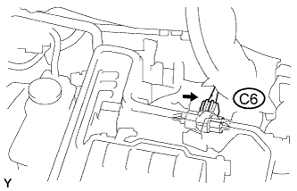 |
Check that the C6 connector is connected securely.
|
| ||||
| NG | |
|
| 11.CHECK INVERTER WITH CONVERTER ASSEMBLY |
|
Disconnect the C6 connector.
Check that the C6 connector terminal does not have burnout.
|
| ||||
| OK | |
|
| 12.CHECK HARNESS AND CONNECTOR (INVERTER WITH CONVERTER ASSEMBLY - BATTERY AND BODY GROUND) |
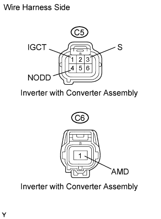 |
Disconnect the C5 and C6 converter inverter connectors.
Turn the power switch ON (IG).
Measure the voltage of the wire harness side connectors.
| Tester Connection | Condition | Specified Condition |
| C5-3 (S) - Body ground | Always | Some as 12 V battery voltage |
| C6-1 (AMD) - Body ground | Always | Some as 12 V battery voltage |
| C5-1 (IGCT) - Body ground | Power switch ON (IG) | 8 to 16 V |
Measure the resistance between the wire harness side connector.
| Tester Connection | Condition | Specified Condition |
| C5-4 (NODD) - Body ground | IG-OFF | 100 to 140 Ω |
|
| ||||
| OK | |
|
| 13.CHECK OPERATION OF INVERTER WITH CONVERTER ASSEMBLY |
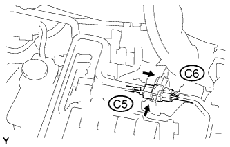 |
Connect the C5 and C6 converter inverter connectors.
Set the electrical tester with the AC/DC 400 A probe to the wire harness of the C6 connector.
Connect the I14 and I15 connectors (color: orange) to the inverter.
Install the inverter cover.
Install the service plug grip.
Turn the power switch ON (READY).
Wait 5 minutes.
Operate the electrical devices as listed below:
Measure the amperage and voltage.
| Item | Specified Condition |
| Output current | 40 to 100 A |
| Item | Specified Condition |
| Battery voltage | 13 to 15 V |
|
| ||||
| NG | |
|
| 14.INSPECT FUSE |
Remove the EPS-H, HEAD MAIN-H, H-LP LO LH, H-LP LO RH, H-LP HI LH, and H-LP HI RH fuses from the engine room relay block.
Remove the DEF-H, PWR-H, FR-DOOR, STOP, M/HTR, A/C (HTR) fuses from the driver side junction block.
Measure the resistance of the fuses.
|
| ||||
| OK | |
|
| 15.CHECK COOLANT LEVEL OF INVERTER WITH CONVERTER ASSEMBLY |
Check the coolant level in the reservoir tank.
|
| ||||
| OK | |
|
| 16.CHECK INVERTER COOLANT HOSE |
Check if the inverter cooling hoses are bent, twisted, damaged or clogged.
|
| ||||
| OK | |
|
| 17.CHECK CONNECTION CONDITION OF WATER PUMP WITH MOTOR CONNECTOR (LOOSENESS AND POOR CONNECTION) |
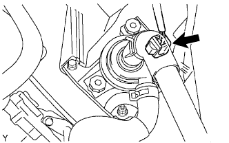 |
Check the connection condition of the pump and bracket connector.
|
| ||||
| OK | |
|
| 18.CHECK OPERATION OF WATER PUMP WITH MOTOR ASSEMBLY |
Turn the power switch ON (IG).
Check the operation of the motor.
|
| ||||
| OK | |
|
| 19.CHECK CONNECTION CONDITION OF COOLING FAN MOTOR CONNECTOR (LOOSENESS AND POOR CONNECTION) |
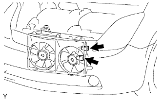 |
Check the connection condition of the fan connectors.
|
| ||||
| OK | |
|
| 20.INSPECT COOLING FAN MOTOR |
Inspect cooling fan motor (Click here).
|
| ||||
| OK | ||
 | ||
| ||
