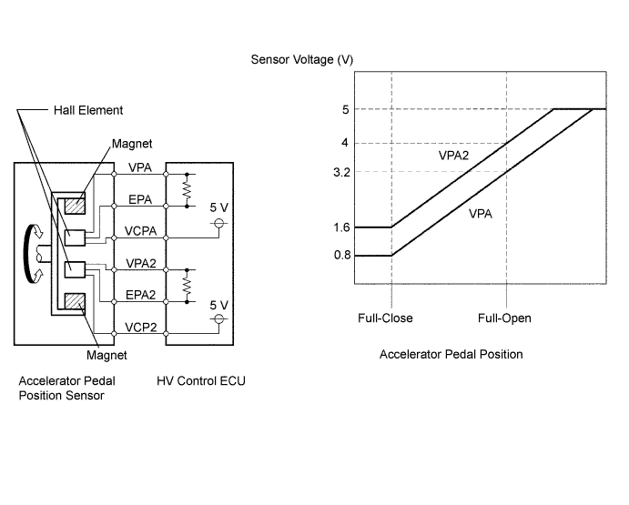
DTC P2122-104 Throttle / Pedal Position Sensor / Switch "D" Circuit Low Input |
DTC P2123-105 Throttle / Pedal Position Sensor / Switch "D" Circuit High Input |
DTC P2127-107 Throttle / Pedal Position Sensor / Switch "E" Circuit Low Input |
DTC P2128-108 Throttle / Pedal Position Sensor / Switch "E" Circuit High Input |
| DTC No. | INF Code | DTC Detection Condition | Trouble Area |
| P2122 | 104 | Open or GND short in accelerator pedal position main sensor circuit |
|
| P2123 | 105 | +B short in accelerator pedal position main sensor circuit |
|
| P2127 | 107 | Open or GND short in accelerator pedal position sub sensor circuit |
|
| P2128 | 108 | +B short in accelerator pedal position sub sensor circuit |
|
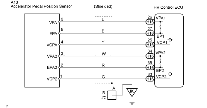
| 1.READ VALUE OF THE TECHSTREAM (ACCEL PEDAL POS #1 AND ACCEL PEDAL POS #2) |
 |
Connect the Techstream to the DLC3.
Turn the power switch ON (IG).
Enter the following menus: Powertrain / Engine Control / Data List.
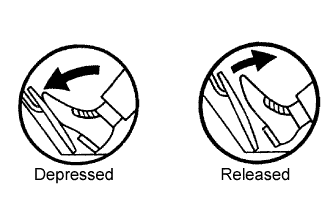
Read the "Accel Pedal Pos #1" and "Accel Pedal Pos #2" values on the Techstream with the engine stopped.
|
| ||||
| NG | |
 |
| 2.CHECK HARNESS AND CONNECTOR (HYBRID VEHICLE CONTROL ECU - ACCELERATOR PEDAL POSITION SENSOR) |
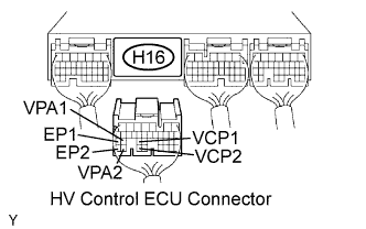 |
Disconnect the H16 HV control ECU connector.
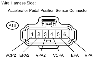 |
Disconnect the A13 accelerator pedal position sensor connector.
Turn the power switch ON (IG).
Measure the voltage between the terminals of the HV control ECU connector and body ground.
| Tester Connection | Specified Condition |
| VPA1 (H16-26) - Body ground | Below 1 V |
| VCP1 (H16-25) - Body ground | Below 1 V |
| EP1 (H16-27) - Body ground | Below 1 V |
| VPA2 (H16-34) - Body ground | Below 1 V |
| VCP2 (H16-33) - Body ground | Below 1 V |
| EP2 (H16-35) - Body ground | Below 1 V |
Turn the power switch OFF.
Measure the resistance between the wire harness side connectors.
| Tester Connection | Specified Condition |
| VPA1 (H16-26) - VPA (A13-6) | Below 1 Ω |
| VCP1 (H16-25) - VCPA (A13-4) | Below 1 Ω |
| EP1 (H16-27) - EPA (A13-5) | Below 1 Ω |
| VPA2 (H16-34) - VPA2 (A13-3) | Below 1 Ω |
| VCP2 (H16-33) - VCP2 (A13-1) | Below 1 Ω |
| EP2 (H16-35) - EPA2 (A13-2) | Below 1 Ω |
| Tester Connection | Specified Condition |
| VPA1 (H16-26) or VPA (A13-6) - Body ground | 10 kΩ or higher |
| VCP1 (H16-25) or VCPA (A13-4) - Body ground | 10 kΩ or higher |
| EP1 (H16-27) or EPA (A13-5) - Body ground | 10 kΩ or higher |
| VPA2 (H16-34) or VPA2 (A13-3) - Body ground | 10 kΩ or higher |
| VCP2 (H16-33) or VCP2 (A13-1) - Body ground | 10 kΩ or higher |
| EP2 (H16-35) or EPA2 (A13-2) - Body ground | 10 kΩ or higher |
Reconnect the accelerator pedal position sensor connector.
Reconnect the HV control ECU connector.
|
| ||||
| OK | |
|
| 3.INSPECT HYBRID VEHICLE CONTROL ECU (VCP1 OR VCP2 VOLTAGE) |
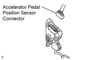 |
Disconnect the A13 accelerator pedal position sensor connector.
Turn the power switch ON (IG).
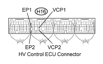 |
Measure the voltage between the terminals of the HV control ECU connector.
| Tester Connection | Specified Condition |
| VCP1 (H16-25) - EP1 (H16-27) | 4.5 to 5.5 V |
| VCP2 (H16-33) - EP2 (H16-35) | 4.5 to 5.5 V |
Reconnect the accelerator pedal position sensor connector.
|
| ||||
| OK | |
|
| 4.REPLACE ACCELERATOR PEDAL ROD |
Replace the Accelerator pedal rod (Click here).
| NEXT | |
|
| 5.CHECK IF DTC OUTPUT RECURS (DTC P2122, P2123, P2127 OR P2128) |
Connect the Techstream to the DLC3.
Turn the power switch ON (IG).
Enter the following menus: Powertrain / Hybrid Control / Trouble Codes.
Perform a simulation test.
Check if DTCs are output.
|
| ||||
| NO | ||
 | ||
| ||

