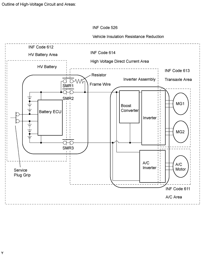
DTC P0AA6-526 Hybrid Battery Voltage System Isolation Fault |
DTC P0AA6-611 Hybrid Battery Voltage System Isolation Fault |
DTC P0AA6-612 Hybrid Battery Voltage System Isolation Fault |
DTC P0AA6-613 Hybrid Battery Voltage System Isolation Fault |
DTC P0AA6-614 Hybrid Battery Voltage System Isolation Fault |
| DTC No. | INF Code | DTC Detection Condition | Trouble Area |
| P0AA6 | 526*1 | Insulation resistance of high voltage circuit and body is low |
|
| P0AA6 | 611*2 | Insulation resistance of A/C compressor motor or A/C inverter is low |
|
| P0AA6 | 612*2 | Insulation resistance of HV battery, battery ECU, system main relay, or system main resistor is low |
|
| P0AA6 | 613*2 | Insulation resistance of HV transaxle or motor and generator inverters is low |
|
| P0AA6 | 614*2 | Insulation resistance of motor and generator inverters, A/C inverter, system main relay, system main resistor, or frame wire is low |
|
| 1.READ OUTPUT DTC (HV ECU) |
Connect the Techstream to the DLC3.
Turn the power switch ON (IG).
Enter the following menus: Powertrain / Hybrid Control / Trouble Codes.
Check if DTCs are output.
| Display (DTC Output) | Proceed to |
| DTC P0AA6 | A |
| DTCs P0AA6 and P0A1D (HV control ECU malfunction) | B |
| DTCs P0AA6 and P0A1F (Battery ECU malfunction) | C |
|
| ||||
|
| ||||
| A | |
 |
| 2.READ OUTPUT INF CODE |
Connect the Techstream to the DLC3.
Turn the power switch ON (IG).
Enter the following menus: Powertrain / Hybrid Control / Trouble Codes.
Display the freeze frame data for DTC P0AA6 and check its information (INF) code.
| Display (INF Code Output) | Proceed to |
| Only 526 (Insulation resistance of high voltage circuit and body is low) | A |
| 526 and 611 (Insulation resistance of A/C area is low) |
Click here
|
| 526 and 612 (Insulation resistance of HV battery area is low) | B |
| 526 and 613 (Insulation resistance of transaxle area is low) | C |
| 526 and 614 (Insulation resistance of high voltage direct current area is low) | D |
|
| ||||
|
| ||||
|
| ||||
| A | |
|
| 3.CHECK ELECTRIC INVERTER COMPRESSOR |
Turn the power switch OFF.
Remove the service plug grip .
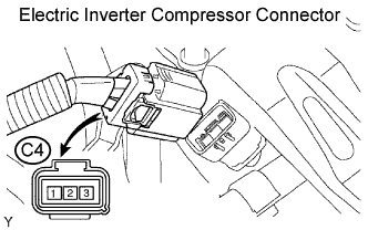 |
Disconnect the C4 electric inverter compressor connector.
Using a megohmmeter, measure the insulation resistance between the high-voltage terminals of the electric inverter compressor connector and the body ground.
| Tester Connection | Specified Condition |
| C4-1 - Body ground | 3.0 MΩ or higher |
| C4-2 - Body ground | 3.0 MΩ or higher |
| C4-3 - Body ground | 3.0 MΩ or higher |
|
| ||||
| OK | |
|
| 4.CHECK INSULATION RESISTANCE (INVERTER, TRANSAXLE AND FRAME WIRE) |
Check that the service plug grip has been detached.
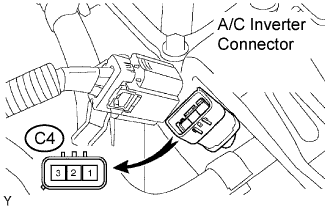 |
Check that the electric inverter compressor connector has been disconnected.
Using a megohmmeter, measure the insulation resistance between the high-voltage terminals of the A/C inverter connector and the body ground.
| Tester Connection | Specified Condition |
| C4-1 - Body ground | 2.0 MΩ or higher |
| C4-2 - Body ground | 2.0 MΩ or higher |
| C4-3 - Body ground | 2.0 MΩ or higher |
|
| ||||
| OK | |
|
| 5.CHECK HV BATTERY AREA |
Turn the power switch OFF.
Check that the service plug grip has been detached. If not, remove the service plug grip .
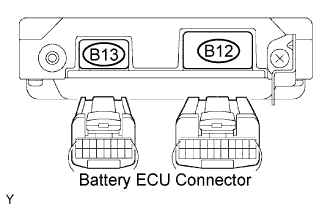 |
Disconnect the B12 and B13 battery ECU connectors.
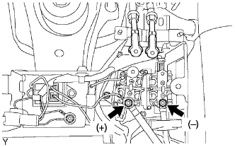 |
Disconnect the main battery cables from the system main relays.
Using a megohmmeter, measure the insulation resistance between the positive terminal on the HV battery side of the system main relay and the body ground.
Using a megohmmeter, measure the insulation resistance between the negative terminal on the HV battery side of the system main relay and the body ground.
|
| ||||
| NG | |
|
| 6.CHECK SYSTEM MAIN RELAYS FOR STICKING |
Check that the service plug grip has been detached.
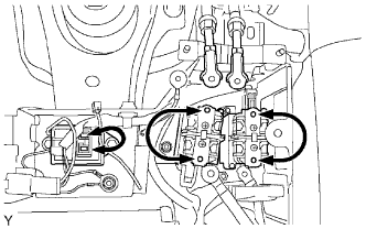 |
Disconnect all the high-voltage terminals of the system main relays.
Measure the resistance at the switch side of the system main relays.
|
| ||||
| OK | |
|
| 7.CHECK SYSTEM MAIN RELAYS FOR INSULATION |
Check that the service plug grip has been detached.
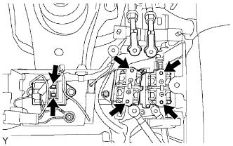 |
Check that all the high-voltage terminals of the system main relays have been disconnected.
Using a megohmmeter, measure the insulation resistance between the high-voltage terminals of the system main relays and the body ground.
|
| ||||
| OK | |
|
| 8.CHECK SYSTEM MAIN RESISTOR FOR INSULATION |
Check that the service plug grip has been detached.
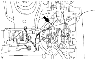 |
Check that both terminals of the system main resistor have been disconnected.
Using a megohmmeter, measure the insulation resistance between the high-voltage terminal of the system main resistor and the body ground.
|
| ||||
| OK | |
|
| 9.INSPECT MAIN BATTERY CABLE |
Remove the HV battery assembly .
Remove the battery cover .
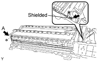 |
Check if the main battery cable cover is not damaged or internal electrical leads are not in contact with the battery case or body.
Remove the terminal (A in the illustration) on the battery module side of the main battery cable only.
Using a megohmmeter, measure the insulation resistance between each terminal of the main battery cable and the shielded ground.
|
| ||||
| OK | |
|
| 10.INSPECT NO. 2 MAIN BATTERY CABLE |
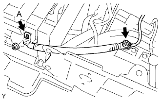 |
Following the previous step, check if the No. 2 main battery cable cover is not damaged or internal electrical leads are not in contact with the battery case or body.
Remove the terminal (A in illustration) on the battery module side of the No. 2 main battery cable only.
Using a megohmmeter, measure the insulation resistance between each terminal of the No. 2 main battery cable and the shielded ground.
|
| ||||
| OK | |
|
| 11.INSPECT BATTERY PLUG |
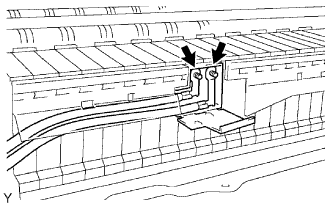 |
Following the previous step, disconnect only the connecting terminal of the battery plug.
Using a megohmmeter, measure the insulation resistance between each terminal of the battery plug wire harness and body ground.
|
| ||||
| OK | |
|
| 12.INSPECT NO. 2 FRAME WIRE |
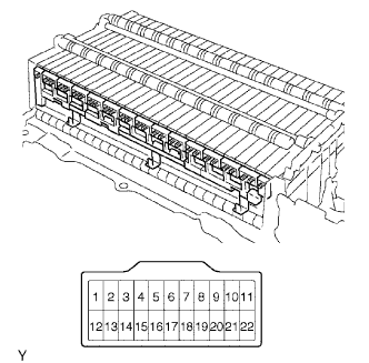 |
Following the previous step, check if the No. 2 frame wire cover is not damaged or internal electrical leads are not in contact with the battery case or body.
Remove all the terminals on the battery module side of the No. 2 frame wire.
Using a megohmmeter, measure the insulation resistance between each terminal of the No. 2 frame wire connector and the battery case.
|
| ||||
| OK | |
|
| 13.INSPECT JUNCTION BLOCK |
Following the previous step, remove the junction block.
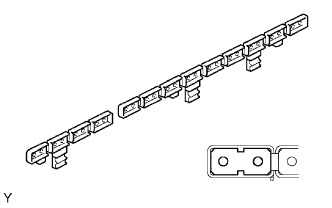 |
Visually check the junction block for any damage.
|
| ||||
| OK | |
|
| 14.INSPECT HV BATTERY ASSEMBLY |
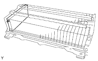 |
Following the previous step, measure the insulation resistance between each terminal (positive and negative side) of each battery module of the HV battery assembly and the battery case using a megohmmeter.
|
| ||||
| OK | ||
 | ||
| ||
| 15.CHECK SYSTEM MAIN RELAYS FOR STICKING |
Check that the service plug grip has been detached.
|
Disconnect all the high-voltage terminals of the system main relays.
Measure the resistance at the switch side of the system main relays.
|
| ||||
| OK | |
|
| 16.CHECK FRAME WIRE FOR INSULATION |
Check that the service plug grip has been detached.
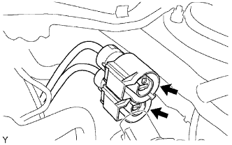 |
Disconnect the frame wire from the inverter.
Using a megohmmeter, measure the insulation resistance between the high-voltage terminals of the frame wire and the body ground.
|
| ||||
| OK | |
|
| 17.CHECK HV TRANSAXLE ASSEMBLY FOR INSULATION |
Check that the service plug grip has been detached.
Remove the inverter cover .
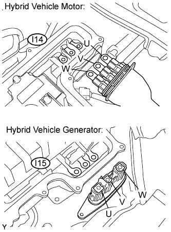 |
Disconnect the three-phase alternating current cables for the motor and generator from the inverter.
Using a megohmmeter, measure the insulation resistance between the 6 terminals of the three-phase alternating current cables on the transaxle side and the body ground.
| Tester Connection | Specified Condition |
| U (I14-1) - Body ground | 10 MΩ or higher |
| V (I14-2) - Body ground | 10 MΩ or higher |
| W (I14-3) - Body ground | 10 MΩ or higher |
| U (I15-1) - Body ground | 10 MΩ or higher |
| V (I15-2) - Body ground | 10 MΩ or higher |
| W (I15-3) - Body ground | 10 MΩ or higher |
|
| ||||
| OK | ||
| ||
| ||
| 18.CHECK HV TRANSAXLE AREA FOR INSULATION |
Turn the power switch OFF.
Remove the service plug grip .
Remove the inverter cover .
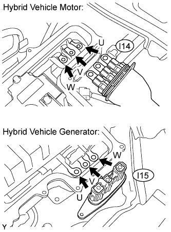 |
Disconnect the three-phase alternating current cables for the motor and generator from the inverter.
Using a megohmmeter, measure the insulation resistance between the 6 terminals of the three-phase alternating current cables on transaxle side and the body ground.
| Tester Connection | Specified Condition |
| U (I14-1) - Body ground | 10 MΩ or higher |
| V (I14-2) - Body ground | 10 MΩ or higher |
| W (I14-3) - Body ground | 10 MΩ or higher |
| U (I15-1) - Body ground | 10 MΩ or higher |
| V (I15-2) - Body ground | 10 MΩ or higher |
| W (I15-3) - Body ground | 10 MΩ or higher |
|
| ||||
| NG | ||
| ||
| ||
| 19.CHECK HIGH VOLTAGE DIRECT CURRENT AREA FOR INSULATION |
Turn the power switch OFF.
Remove the service plug grip .
|
Disconnect the frame wire from the inverter.
Using a megohmmeter, measure the insulation resistance between the high-voltage terminals of the frame wire and the body ground.
|
| ||||
| NG | |
|
| 20.CHECK FRAME WIRE FOR INSULATION |
Check that the service plug grip has been detached.
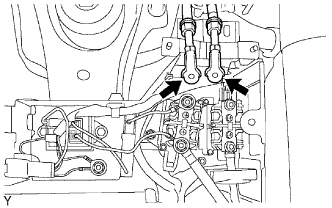 |
Disconnect the frame wire from the system main relays.
Using a megohmmeter, measure the insulation resistance between the high-voltage terminals of the frame wire and the body ground.
|
| ||||
| OK | |
|
| 21.CHECK SYSTEM MAIN RELAYS FOR STICKING |
Check that the service plug grip has been detached.
|
Disconnect all the high-voltage terminals of the system main relays.
Measure the resistance at the switch side of the system main relays.
|
| ||||
| OK | |
|
| 22.CHECK SYSTEM MAIN RELAYS FOR INSULATION |
Check that the service plug grip has been detached.
Check that all the high-voltage terminals of the system main relays have been disconnected.
|
Using a megohmmeter, measure the insulation resistance between the high-voltage terminals of the system main relays and the body ground.
|
| ||||
| OK | |
|
| 23.CHECK SYSTEM MAIN RESISTOR FOR INSULATION |
Check that the service plug grip has been detached.
|
Check that both terminals of the system main resistor have been disconnected.
Using a megohmmeter, measure the insulation resistance between the high-voltage terminal of the system main resistor and the body ground.
|
| ||||
| OK | |
|
| 24.INSPECT MAIN BATTERY CABLE |
|
Remove the HV battery assembly .
Remove the battery cover .
Check if the main battery cable cover is not damaged or internal electrical leads are not in contact with the battery case or body.
Remove the terminal (A in the illustration) on the battery module side of the main battery cable only.
Using a megohmmeter, measure the insulation resistance between each terminal of the main battery cable and the shielded ground.
|
| ||||
| OK | |
|
| 25.INSPECT NO. 2 MAIN BATTERY CABLE |
Following the previous step, check if the No. 2 main battery cable cover is not damaged or internal electrical leads are not in contact with the battery case or body.
|
Remove the terminal (A in illustration) on the battery module side of the No. 2 main battery cable only.
Using a megohmmeter, measure the insulation resistance between each terminal of the No. 2 main battery cable and the shielded ground.
|
| ||||
| OK | |
|
| Go to step 28 |
| 26.INSPECT BATTERY PLUG |
|
Following the previous step, disconnect only the connecting terminal of the battery plug.
Using a megohmmeter, measure the insulation resistance between each terminal of the battery plug wire harness and the body ground.
|
| ||||
| OK | |
|
| 27.INSPECT NO. 2 FRAME WIRE |
|
Following the previous step, check if the No. 2 frame wire cover is not damaged or internal electrical leads are not in contact with the battery case or body.
Remove all the terminals on the battery module side of the No. 2 frame wire.
Using a megohmmeter, measure the insulation resistance between each terminal of the No. 2 frame wire connector and the battery case.
|
| ||||
| OK | |
|
| 28.INSPECT JUNCTION BLOCK |
|
Following the previous step, remove the junction block.
Visually check the junction block for any damage.
|
| ||||
| OK | |
|
| 29.INSPECT HV BATTERY ASSEMBLY |
|
Following the previous step, measure the insulation resistance between each terminal (positive and negative side) of each battery module of the HV battery assembly and the battery case using a megohmmeter.
|
| ||||
| OK | ||
| ||
| ||

