| NG |  |
| ADD HV COOLANT |
DTC P0AEE-276 Motor Inverter Temperature Sensor "A" Circuit Range / Performance |
DTC P0AEE-277 Motor Inverter Temperature Sensor "A" Circuit Range / Performance |
| DTC No. | INF Code | DTC Detection Condition | Trouble Area |
| P0AEE | 276 | Sudden change in motor inverter temperature sensor output |
|
| P0AEE | 277 | Motor inverter temperature sensor output deviation |
|
| 1.CHECK QUANTITY OF HV COOLANT |
Check that there is a sufficient amount of coolant for the inverter.
|
| ||||
| OK | |
 |
| 2.CHECK COOLANT HOSE |
Check that the hoses of the cooling system are not bent or clogged (refer to the cooling system [Click here]).
|
| ||||
| OK | |
|
| 3.CHECK CONNECTION CONDITION OF WATER PUMP CONNECTOR (LOOSENESS AND POOR CONTACT) |
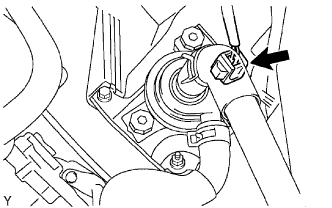 |
Check the connection condition of the water pump connector.
|
| ||||
| OK | |
|
| 4.CHECK WATER PUMP WITH MOTOR ASSEMBLY |
Turn the power switch ON (IG).
Check the operation of the water pump.
|
| ||||
| OK | |
|
| 5.CHECK CONNECTION CONDITION OF COOLING FAN MOTOR CONNECTOR (LOOSENESS AND POOR CONTACT) |
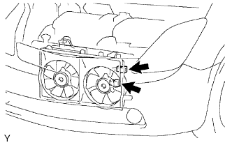 |
Check the connection condition of the cooling fan motor connectors.
|
| ||||
| OK | |
|
| 6.INSPECT COOLING FAN MOTOR |
Inspect the cooling fan motor .
|
| ||||
| OK | |
|
| 7.INSPECT NO. 2 COOLING FAN MOTOR |
Inspect the No. 2 cooling fan motor .
|
| ||||
| OK | |
|
| 8.CHECK CONNECTION CONDITION OF HYBRID VEHICLE CONTROL ECU CONNECTOR (LOOSENESS AND POOR CONTACT) |
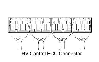 |
Check the connection condition of all the connectors at the HV control ECU.
|
| ||||
| OK | |
|
| 9.CHECK CONNECTION CONDITION OF INVERTER CONNECTOR (LOOSENESS AND POOR CONTACT) |
Turn the power switch OFF.
Remove the service plug grip .
Remove the inverter cover .
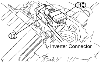 |
Check the connection condition of the I9 and I10 inverter connectors.
|
| ||||
| OK | |
|
| 10.CHECK HARNESS AND CONNECTOR (HYBRID VEHICLE CONTROL ECU - INVERTER) |
Check that the service plug grip and inverter cover have been removed.
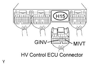 |
Disconnect the H15 HV control ECU connector.
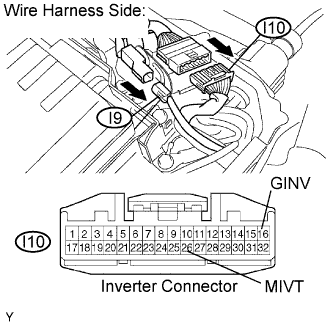 |
Disconnect the I9 and I10 inverter connectors.
Turn the power switch ON (IG).
Measure the voltage between the terminals of the HV control ECU connector and body ground.
| Tester Connection | Specified Condition |
| MIVT (H15-19) - Body ground | Below 1 V |
| GINV (H15-23) - Body ground | Below 1 V |
Turn the power switch OFF.
Measure the resistance between the wire harness side connectors.
| Tester Connection | Specified Condition |
| MIVT (H15-19) - MIVT (I10-26) | Below 1 Ω |
| GINV (H15-23) - GINV (I10-16) | Below 1 Ω |
| Tester Connection | Specified Condition |
| MIVT (H15-19) or MIVT (I10-26) - Body ground | 10 kΩ or higher |
| GINV (H15-23) or GINV (I10-16) - Body ground | 10 kΩ or higher |
Reconnect the inverter connectors.
Reconnect the HV control ECU connector.
Reinstall the inverter cover .
Reinstall the service plug grip .
|
| ||||
| OK | ||
 | ||
| ||