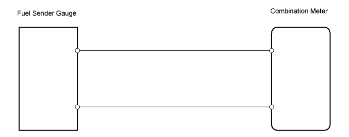
METER / GAUGE SYSTEM > Fuel Receiver Gauge Malfunction |
| 1.CHECK COMBINATION METER |
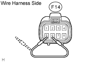 |
Disconnect the F14 sender gauge connector.
Turn the power switch ON (IG), and check the position of the sender gauge segment.
| Condition | Display |
| Before disconnecting connector, 1 segment is blinking | Segment blinks for 60 seconds, then changes to a different blinking cycle |
| Before disconnecting connector, other than 1 blinking segment is displayed | Current display continues for 60 seconds, then begins blinking |
Connect terminals 5 and 6 on the wire harness side connector.
Turn the power switch ON (IG), and check the position of the receiver gauge segment.
| Condition | Display |
| Before disconnecting connector, all 10 segments are displayed | All 10 segments illuminate for 60 seconds, then begin blinking |
| Before disconnecting connector, less than 10 segments are displayed | Gauge increases to 9 segments, then begins blinking after 60 seconds |
Measure the voltage of the wire harness side connector.
| Tester Connection | Switch Condition | Specified Condition |
| F14-5 - Body ground | Power switch ON (IG) | 10 to 14 V |
|
| ||||
| OK | |
 |
| 2.INSPECT FUEL SENDER GAUGE ASSEMBLY |
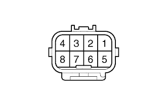 |
Disconnect the F14 gauge connector.
Measure the resistance of the gauge connector.
| Tester Connection | Fuel level | Specified Condition |
| 5 - 6 | Full | Approx. 4 Ω |
| Half | Approx. 40 to 60 Ω | |
| Empty | Approx. 110 Ω |
|
| ||||
| OK | ||
 | ||
| ||
| 3.CHECK WIRE HARNESS (GAUGE - METER) |
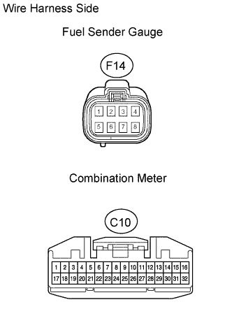 |
Disconnect the F14 gauge connector.
Disconnect the C12 meter connector.
Measure the resistance of the wire harness side connectors.
| Tester Connection | Specified Condition |
| F14-6 - C10-31 | Below 1 Ω |
| F14-5 - C10-15 |
|
| ||||
| OK | ||
| ||
| ||

