 |
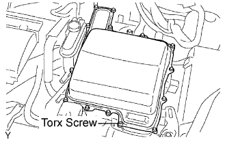
Remove the inverter cover.
Using a T30 "torx" socket, remove the screw.
Remove the 12 bolts and inverter cover.
INVERTER WITH CONVERTER > ON-VEHICLE INSPECTION |
| 1. INSPECT INVERTER |
Turn the power switch OFF.
Remove the service plug grip (Click here).
|
Remove the inverter cover.
Using a T30 "torx" socket, remove the screw.
Remove the 12 bolts and inverter cover.
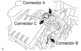 |
Disconnect connectors A and B shown in the illustration.
Turn the power switch ON (IG).
If turning the power switch ON (IG) with the service plug grip removed, the DTC of the interlock switch system will be output.
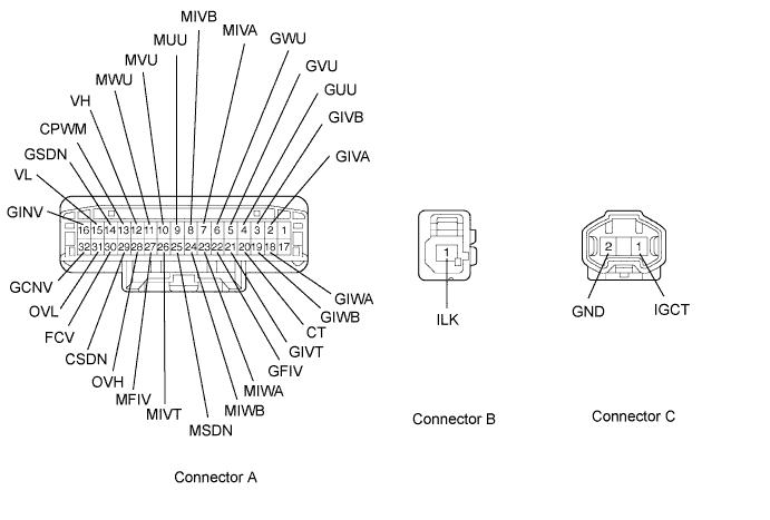
Using a voltmeter, measure the voltage. Also, using an ohmmeter, measure the resistance.
| Tester Connection | Measuring Condition | Specified Condition |
| A-2 (GIVA) - A-16 (GINV) | - | Approximately 0 V |
| A-3 (GIVB) - A-16 (GINV) | - | Approximately 0 V |
| A-4 (GUU) - A-16 (GINV) | - | Approximately 14 to 16 V |
| A-5 (GVU) - A-16 (GINV) | - | Approximately 14 to 16 V |
| A-6 (GWU) - A-16 (GINV) | - | Approximately14 to 16 V |
| A-7 (MIVA) - A-16 (GINV) | - | Approximately 0 V |
| A-8 (MIVB) - A-16 (GINV) | - | Approximately 0 V |
| A-9 (MUU) - A-16 (GINV) | - | Approximately 14 to 16 V |
| A-10 (MVU) - A-16 (GINV) | - | Approximately 14 to 16 V |
| A-11 (MWU) - A-16 (GINV) | - | Approximately 14 to 16 V |
| A-12 (VH) - A-16 (GINV) | - | Approximately 0.5 V |
| A-13 (CPWM) - A-32 (GCNV) | - | Approximately 0 V |
| A-14 (GSDN) - A-32 (GCNV) | - | Approximately 2 to 4.5 V |
| A-15 (VL) - A-32 (GCNV) | - | Approximately 0.5 V |
| A-16 (GINV) - C-2 (GND) | - | Approximately 0 V |
| A-18 (GIWA) - A-16 (GINV) | - | Approximately 0 V |
| A-19 (GIWB) - A-16 (GINV) | - | Approximately 0 V |
| A-20 (CT) - A-16 (GINV) | - | Approximately 0 V |
| A-21 (GIVT) - A-16 (GINV) | - | Approximately 2 to 4.5 V |
| A-22 (GFIV) - A-16 (GINV) | - | Approximately 5 to 8 V |
| A-23 (MIWA) - A-16 (GINV) | - | Approximately 0 V |
| A-24 (MIWB) - A-16 (GINV) | - | Approximately 0 V |
| A-25 (MSDN) - A-16 (GINV) | - | Approximately 0 V |
| A-26 (MIVT) - A-16 (GINV) | - | Approximately 2 to 4.5 V |
| A-27 (MFIV) - A-16 (GINV) | - | Approximately 5 to 8 V |
| A-28 (OVH) - A-16 (GINV) | - | Approximately 5 to 8 V |
| A-29 (CSDN) - A-32 (GCNV) | - | Approximately 0 V |
| A-30 (FCV) - A-32 (GCNV) | - | Approximately 13.5 to 16.5 V |
| A-31 (OVL) - A-32 (GCNV) | - | Approximately 13.5 to 16.5 V |
| A-32 (GCNV) - C-2 (GND) | - | Approximately 0 V |
| B-1 (ILK) - Body ground | After installing the probe to the terminal, temporarily install the inverter cover. It does not have to be tightened with the bolts at this point. | Below 1 Ω |
| C-1 (IGCT) - C-2 (GND) | - | Approximately 8 to 16 V |
| C-2 (GND) - Body ground | - | Below 1 Ω |
| 2. INSPECT CONVERTER |
 |
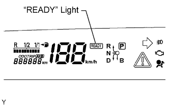 |
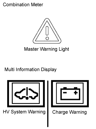
Check the operation.
Using a voltmeter, measure the voltage of the auxiliary battery terminal when the "READY" light is OFF and ON.
| "READY" Light | Specified Condition |
| ON | 14 V |
| OFF | 12 V |
Inspect the output current.
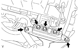 |
Remove the 5 bolts, and disconnect the MG1 power cables from the inverter.
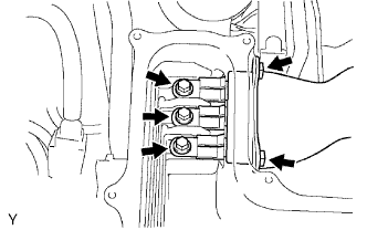 |
Remove the 5 bolts, and disconnect the MG2 power cable.
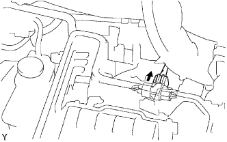 |
Install a voltmeter and the AC/DC 400 A probe to the locations shown in the illustration.
Connect the MG1 power cable to the MG1 power cable terminal with the 5 bolts.
Connect the MG2 power cable to the MG2 power cable terminal with the 3 bolts.
With the "READY" light ON, operate the 12 V electrical devices one by one, and then measure the output current.
|
Check the input/output signal.
Disconnect the connectors shown in the illustration.
Using a voltmeter, measure the voltage between the body ground and the terminal of the vehicle side wire harness connector.
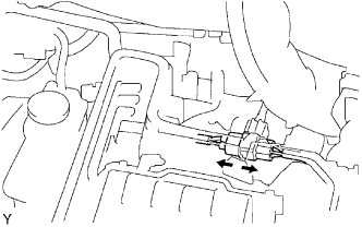 |
Disconnect the connectors shown in the illustration.
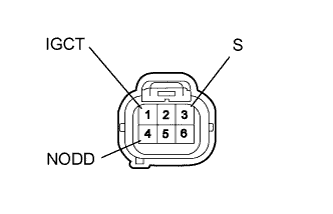 |
Turn the power switch ON (IG). Using a voltmeter and ohmmeter, measure the voltage and resistance between the connector terminals on the vehicle harness side.
| Tester Connection | Specified Condition |
| 1 (IGCT) - Body ground | 8 to 16 V |
| 3 (S) - Body ground | Equal to the auxiliary battery voltage |
| 4 (NODD) - Body ground | 120 to 140 kΩ (when power switch is OFF) |