 |
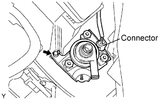
Connect the connector.
WATER PUMP WITH MOTOR > INSTALLATION |
| 1. INSTALL WATER PUMP WITH MOTOR ASSEMBLY |
|
Connect the connector.
Install the water pump with motor assembly with the bolt.
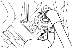 |
Connect the 2 inverter cooling hoses.
| 2. INSTALL WATER VALVE WITH BRACKET ASSEMBLY |
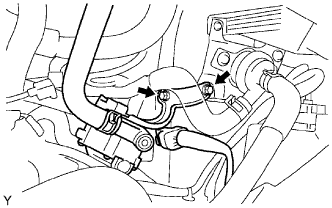 |
Install the water valve with the bolt and nut.
| 3. INSTALL HEADLIGHT ASSEMBLY LH |
Install the headlight LH to the vehicle (Click here).
| 4. INSTALL FRONT BUMPER ENERGY ABSORBER |
| 5. INSTALL FRONT BUMPER COVER |
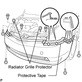 |
Put protective tape under the front fender.
w/ Fog light:
Connect the 2 fog light connectors.
Attach the 12 claws to install the bumper cover.
Install the 4 screws and 3 clips.
Install the 2 radiator grille protectors.
| 6. INSTALL FRONT SPOILER COVER |
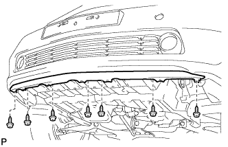 |
Install the spoiler cover with the 7 screws.
| 7. INSTALL CENTER NO. 4 ENGINE UNDER COVER |
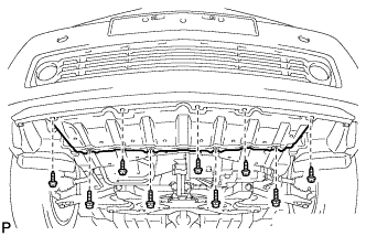 |
Install the under cover with the 5 screws and 4 bolts.
| 8. INSTALL FRONT FENDER LINER LH |
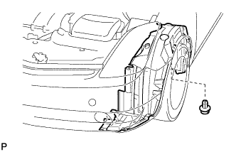 |
Install the fender liner with the clip.
| 9. INSTALL FRONT FENDER LINER RH |
| 10. ADD COOLANT (for Inverter) |
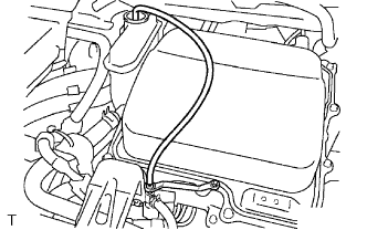 |
Loosen the bleeder plug shown in the illustration and connect a hose.
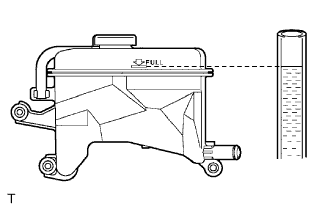 |
Add coolant until the level of coolant in the hose attached to the bleeder tank reaches the same level as the FULL line of the reserve tank.
Close the bleeder plug.
Turn the power switch ON (IG) and run the water pump for approximately 20 seconds.
Turn the power switch OFF. (*1)
Loosen the bleeder plug and bleed the air from the transaxle. (*2)
Add coolant into the bleeder tank. (*3)
Repeat the steps *1, *2 and *3.
Turn the power switch ON (IG) and run the water pump for approximately 5 minutes after completing air bleeding of the coolant system.
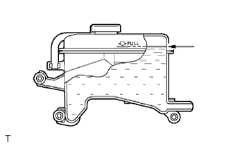 |
Add coolant until the reserve tank is filled up to the FULL mark.
| 11. INSPECT FOR COOLANT (for Inverter) |
| 12. CONNECT CABLE TO NEGATIVE BATTERY TERMINAL |
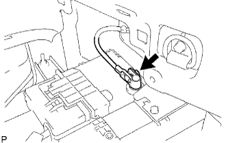 |
Connect the battery negative cable, and then tighten the nut.
| 13. INSTALL REAR NO. 3 FLOOR BOARD |
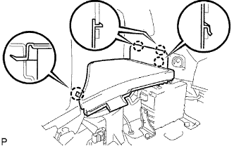 |
Install the floor board, and then attach the 4 claws.
| 14. INSTALL REAR DECK FLOOR BOX |
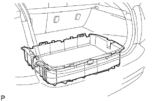 |
Install the rear deck floor box to the vehicle.
| 15. INSTALL REAR NO. 2 FLOOR BOARD |
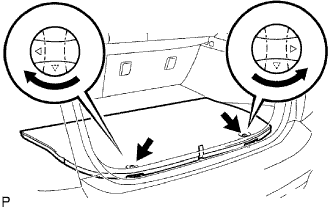 |
Install the floor board, and then lock the 2 cover knobs.
| 16. PERFORM INITIALIZATION |
Perform initialization (Click here).