MAIN BATTERY CABLE > INSTALLATION |
| 1. INSTALL NO. 2 MAIN BATTERY CABLE |
|
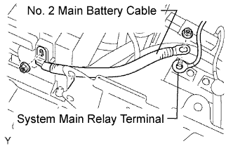
Temporarily install the No. 2 main battery cable to the HV battery.
Install the No. 2 main battery cable to the No. 2 frame wire with a new nut.
Temporarily install the main battery cable and system main relay terminal, in that order, to the No. 2 system main relay, then tighten the new nut.
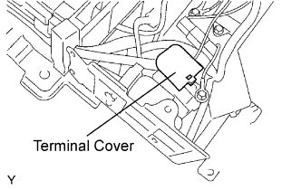 |
Install the terminal cover shown in the illustration.
| 2. INSTALL MAIN BATTERY CABLE |
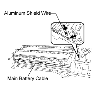 |
Temporarily install the main battery cable to the HV battery.
Install the main battery cable to the No. 2 frame wire with a new nut.
Install the main battery cable to the No. 3 system main relay with a new nut.
Install the aluminum shield wire with a new nut.
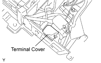 |
Install the terminal cover shown in the illustration.
| 3. INSTALL NO. 3 BATTERY CARRIER CUSHION |
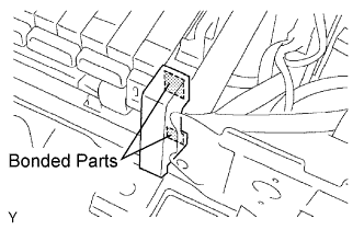 |
Degrease and clean the installation surface of the battery carrier cushion.
Install a new battery carrier cushion.
| 4. INSTALL NO. 1 WIRE HARNESS PROTECTOR COVER |
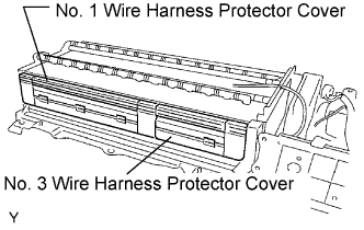 |
| 5. INSTALL NO. 3 WIRE HARNESS PROTECTOR COVER |
| 6. INSTALL BATTERY COVER |
Temporarily fasten the battery carrier catch bracket to the battery room ventilation hose.
Install the battery cover with the 6 bolts, 2 nuts and clip.
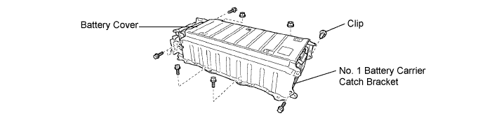
Install the protector on the battery cover.
| 7. INSTALL HV BATTERY ASSEMBLY |
Install the HV battery to the vehicle (Click here).
| 8. INSTALL SERVICE PLUG GRIP |
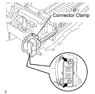 |
Temporarily fasten the service plug.
Install the service plug to the upper battery carrier with the 2 bolts.
Assemble the connector clamp.
| 9. CONNECT CABLE TO NEGATIVE BATTERY TERMINAL |
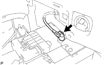 |
Connect the battery negative cable, and then tighten the nut.
| 10. INSTALL REAR NO. 3 FLOOR BOARD |
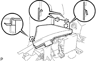 |
Install the floor board, and then attach the 4 claws.
| 11. INSTALL REAR DECK FLOOR BOX |
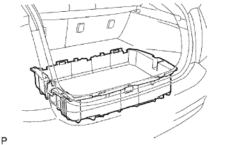 |
Install the rear deck floor box to the vehicle.
| 12. INSTALL REAR NO. 2 FLOOR BOARD |
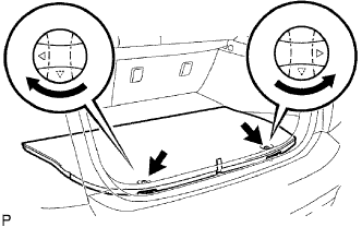 |
Install the floor board, and then lock the 2 cover knobs.
| 13. PERFORM INITIALIZATION |
Perform initialization (Click here).