Home › HYBRID SYSTEM › P112 HYBRID BATTERY CONTROL › JUNCTION BLOCK

JUNCTION BLOCK > INSTALLATION

for Preparation Click here


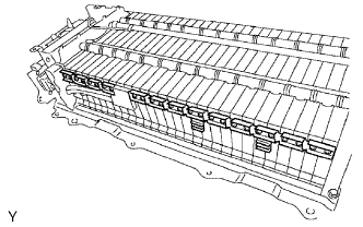
1. INSTALL JUNCTION BLOCK


A083549E01

CAUTION:
Wear insulating gloves.

  1. Install the junction block assembly with 26 new nuts.

    Torque:
    5.4 N*m{ 55 kgf*cm , 48 in.*lbf }


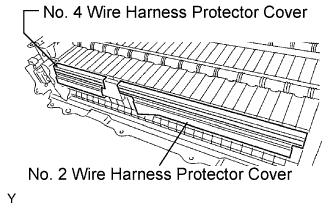
2. INSTALL NO. 2 WIRE HARNESS PROTECTOR COVER


A083565E02

CAUTION:
Wear insulating gloves.


3. INSTALL NO. 4 WIRE HARNESS PROTECTOR COVER

CAUTION:
Wear insulating gloves.


4. INSTALL BATTERY COVER

CAUTION:
Wear insulating gloves.

  1. Temporarily fasten the battery carrier catch bracket to the battery room ventilation hose.


  1. Install the battery cover with the 6 bolts, 2 nuts and clip.
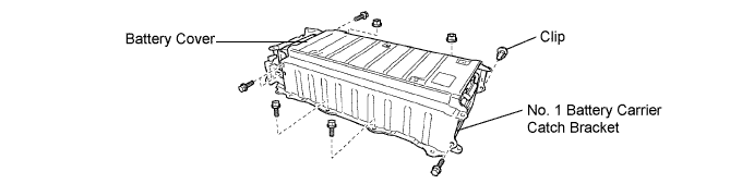

    A083611E01

    Torque:
    8.0 N*m{ 82 kgf*cm , 71 in.*lbf }

  1. Install the protector on the battery cover.


5. INSTALL HV BATTERY ASSEMBLY
  1. Install the HV battery to the vehicle (Click here).


6. INSTALL SERVICE PLUG GRIP

CAUTION:
Wear insulating gloves.

  1. Joint the service plug grip with the HV battery.

  1. While pushing the service plug grip to the right, rotate the lever to the right.

  1. Slide the lever down to lock the service plug grip in place.
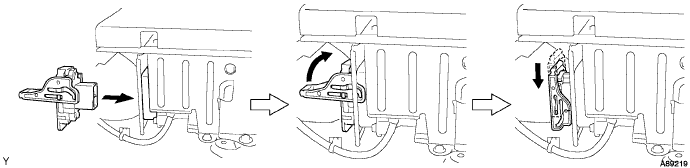
    NOTICE:
    1. The service plug grip must be locked. If not, it may cause DTCs to output.

    2. Do not operate the power switch when the service plug grip is not properly locked. It may damage the hybrid vehicle control ECU in rare cases.


      A089219


7. CONNECT CABLE TO NEGATIVE BATTERY TERMINAL

NOTICE:
  1. When the warning light is illuminated or the battery has been disconnected and reconnected, turning the power switch may not start the system on the first try. If so, turn the power switch again.
  2. With the power switch's power mode changed to ON (IG), disconnect the battery. If the key is not in the key slot during reconnection, DTC B2799 may be output.


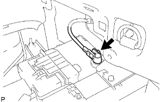
    A088356E01
  1. Connect the battery negative cable, and then tighten the nut.

    Torque:
    6.0 N*m{ 61 kgf*cm , 53 in.*lbf }


8. INSTALL REAR NO. 3 FLOOR BOARD


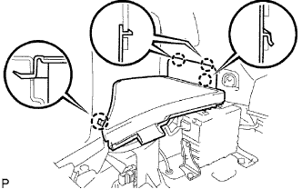
    A088355E02
  1. Install the floor board, and then attach the 4 claws.


9. INSTALL REAR DECK FLOOR BOX


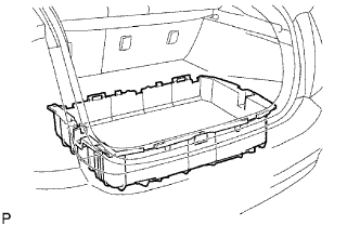
    A088354E01
  1. Install the rear deck floor box to the vehicle.


10. INSTALL REAR NO. 2 FLOOR BOARD


    A088353E01
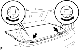
  1. Install the floor board, and then lock the 2 cover knobs.


11. PERFORM INITIALIZATION
  1. Perform initialization (Click here).

    NOTICE:
    Certain systems need to be initialized after disconnecting and reconnecting the cable from the negative (-) battery terminal.