Home › ENGINE › 1NZ-FXE ENGINE CONTROL SYSTEM › SFI SYSTEM

DTC    P1150    Coolant Path Clog of Coolant Heat Storage System

for Preparation Click here


DESCRIPTION


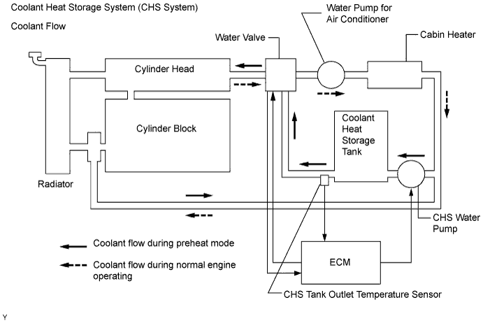
A082803E01

This system uses an electric pump to supply hot coolant stored in the coolant heat storage (CHS) tank into the cylinder head of the engine, in order to optimize engine starting combustion and reduce the amount of unburned gas that is discharged while the engine is started. Before the engine starts, the ECM operates the electric water pump to direct the hot coolant in the CHS tank into the engine, in order to heat the cylinder head (this process is called "preheat mode"). The duration of the operation of the electric water pump is variable, depending on the temperature of the cylinder head. During normal operation of the engine, the water valve opens the passage between the cylinder head and the heater and closes the passage between the cylinder head and the tank. During the preheat mode in which the cylinder head is heated, the water valve opens the passage between the tank and the cylinder head, in order to allow the coolant to flow from the tank to the cylinder head. At this time, in order to warm up the intake port quickly before the engine is started, the coolant flows in the reverse direction.
This system consists of the CHS tank, CHS water pump, CHS tank outlet temperature sensor, water valve, and a soak timer that is built in the ECM.

DTC No.
DTC Detection Condition
Trouble Area
P1150
Following conditions are met:
  1. Change in CHS tank outlet temperature and engine coolant temperature after water pump is ON during preheat mode: below 2°C (3.6°F)
  2. Change in CHS tank outlet temperature as water valve is opened to tank, on a warm engine: below 3°C (5.4°F)
  1. CHS tank outlet temperature sensor
  2. Water valve (coolant flow control valve)
  3. Cooling system (clogging)
  4. ECM

MONITOR DESCRIPTION

The ECM detects a malfunction in the coolant heat storage (CHS) system with the CHS tank outlet temperature signal, the position of the water valve and the engine running condition. In order to ensure the reliable malfunction detection, the ECM detects coolant passage clogging malfunction in two ways. Thus, when the following two detection conditions are met, the ECM determines that the coolant passage has clogged and sets a DTC.
  1. When starting the engine, a variation in the CHS tank outlet temperature and engine coolant temperature before and after preheating is below 2°C (3.6°F).
  2. After the engine is warmed up, a variation in the CHS tank outlet temperature when the ECM opens the water valve is below 3°C (5.4°F).

MONITOR STRATEGY


Related DTCs
P1150: Coolant path clog up for coolant heat storage system
Required sensors/components (main)
CHS tank outlet temperature sensor
Frequency of operation
Once per driving cycle
Duration
10 seconds
MIL operation
1 driving cycle
Sequence of operation
None

TYPICAL ENABLING CONDITIONS


The monitor will run whenever the following DTCs are not present
None
Coolant heat storage system malfunction
Not detected
Coolant heat storage water pump operation time
3 seconds or more
Variation in CHS tank coolant temperature and engine coolant temperature before and after preheating
2°C (3.6°F) or less
Engine coolant temperature
65°C (149°F) or more

TYPICAL MALFUNCTION THRESHOLDS


Variation in CHS tank coolant temperature during passage clogging check
Less than 3°C (5.4°F)

WIRING DIAGRAM

Refer to DTC P1120 .

INSPECTION PROCEDURE

CAUTION:
Be careful when replacing any part in the system or changing the coolant because the coolant in the heat storage tank is hot even if the engine and the radiator are cold.

HINT:
  1. The detection of this DTC may indicate that the coolant heat storage (CHS) tank outlet water temperature sensor stuck or the water valve stuck.
  2. If DTC P1121 is detected, coolant passages may be clogged.
  3. To check the coolant heat storage (CHS) system, the ECM may cause the water pump of the CHS system to operate 5 hours after the power switch has been turned OFF.
  4. Read freeze frame data using Techstream. The ECM records vehicle and driving condition information as freeze frame data the moment a DTC is stored. When troubleshooting, freeze frame data can be helpful in determining whether the vehicle was running or stopped, whether the engine was warmed up or not, whether the air/fuel ratio was lean or rich, as well as other data recorded at the time of a malfunction.

1.CHECK OTHER DTC OUTPUT (IN ADDITION TO DTC P1150)
  1. Connect Techstream to the DLC3.

  1. Turn the power switch ON (IG).

  1. Turn the tester ON.

  1. Enter the following menus: Powertrain / Engine and ECT / Trouble Code.

  1. Read DTCs.

    Result:
    Display (DTC Output)
    Proceed to
    P1150
    A
    P1150 and other DTCs
    B

    HINT:
    If any other codes besides P1150 are output, perform troubleshooting for those DTCs first.


B
GO TO DTC CHART
A


2.PERFORM ACTIVE TEST BY TECHSTREAM
A124045E10
  1. Connect Techstream to the DLC3.

  1. Turn the power switch ON (IG).

  1. Turn the tester ON.

  1. Put the engine in inspection mode (Click here).

  1. Start the engine and warm it up.

  1. Enter the following menus: Powertrain / Engine and ECT / Active Test / Activate the Water Flow Valve 3, Activate the Water Flow Valve 4 or Activate the Water Flow Valve 5.

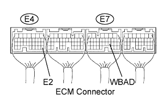
  1. Measure the voltage between terminals WBAD and E2 of the ECM connector.

    Standard voltage:
    Tester Operation
    Specified Condition
    "Water Flow Valve 3" ON
    Approximately 2.5 V
    "Water Flow Valve 4" ON
    Approximately 3.5 V
    "Water Flow Valve 5" ON
    Approximately 4.5 V


NG
REPLACE WATER W/BRACKET VALVE ASSEMBLY
OK


3.INSPECT TEMPERATURE SENSOR


    A081700E08
  1. Remove the CHS tank outlet temperature sensor.

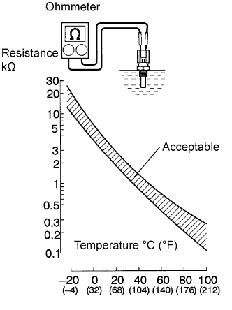
  1. Measure the resistance between the terminals.

    Standard resistance:
    Tester Connection
    Specified Condition
    1 - 2
    2 to 3 kΩ at 20°C (68°F)
    1 - 2
    0.2 to 0.4 kΩ at 80°C (176°F)

    NOTICE:
    In case of checking the CHS tank outlet temperature sensor in the water, be careful not to allow water to contact the terminals. After checking, dry the sensor.

    HINT:
    Alternate procedure: Connect an ohmmeter to the installed CHS tank outlet temperature sensor and read the resistance. Use an infrared thermometer to measure the CHS tank outlet temperature in the immediate vicinity of the sensor. Compare these values to the resistance/temperature graph. Change the engine temperature (warm up or allow to cool down) and repeat the test.

  1. Reinstall the CHS tank outlet temperature sensor.


NG
REPLACE TEMPERATURE SENSOR
OK

CHECK COOLING SYSTEM (CHECK FOR CLOGGING IN THE COOLING SYSTEM)