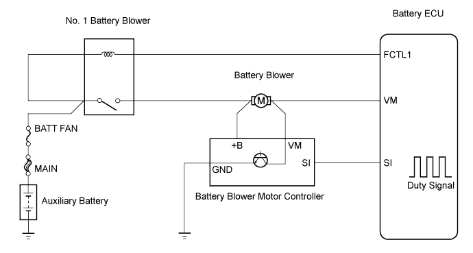
DTC P0A84 Hybrid Battery Pack Cooling Fan 1 Control Circuit Low |
DTC P0A85 Hybrid Battery Pack Cooling Fan 1 Control Circuit High |
| DTC No. | DTC Detection Condition | Trouble Area |
| P0A84 | Battery blower voltage is lower than malfunction threshold at constant vehicle speed |
|
| P0A85 | Battery blower voltage is higher than malfunction threshold at constant vehicle speed |
|
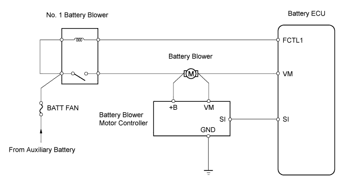
| 1.CHECK FUSE (BATT FAN) |
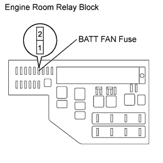 |
Remove the BATT FAN fuse from the engine room relay block.
Measure the resistance of the BATT FAN fuse.
Reinstall the BATT FAN fuse.
|
| ||||
| OK | |
 |
| 2.INSPECT NO. 1 BATTERY BLOWER RELAY |
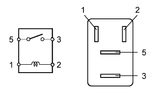 |
Remove the No. 1 battery blower relay.
Measure the resistance of the terminals of the relay.
| Tester Connection | Specified Condition |
| 3 - 5 | 10 kΩ or higher |
| 3 - 5 | Below 1 Ω (Apply battery voltage to terminals 1 and 2) |
Reinstall the No. 1 battery blower relay.
|
| ||||
| OK | |
|
| 3.INSPECT BATTERY BLOWER |
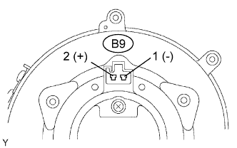 |
Disconnect the B9 battery blower connector.
Connect the positive terminal of the battery to terminal 2 of the battery blower connector, and the negative battery terminal to terminal 1 of the connector.
Check that the blower fan rotates when voltage is applied.
|
| ||||
| OK | |
|
| 4.CHECK BATTERY BLOWER MOTOR CONTROLLER |
Check the battery blower motor controller (Click here).
|
| ||||
| OK | |
|
| 5.CHECK WIRE HARNESS (NO. 1 BATTERY BLOWER RELAY - BATT FAN FUSE) |
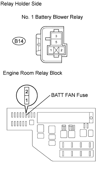 |
Remove the B14 No. 1 battery blower relay.
Remove the BATT FAN fuse from the engine room relay block.
Measure the resistance of the wire harness side connectors.
| Tester Connection | Specified Condition |
| B14-1 and 3 - BATT FAN fuse terminal 2 | Below 1 Ω |
Reinstall the No. 1 battery blower relay.
Reinstall the BATT FAN fuse.
|
| ||||
| OK | |
|
| 6.CHECK WIRE HARNESS (NO. 1 BATTERY BLOWER RELAY - BATTERY BLOWER) |
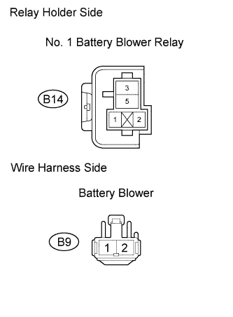 |
Remove the B14 No. 1 battery blower relay.
Disconnect the B9 battery blower connector.
Measure the resistance of the wire harness side connectors.
| Tester Connection | Specified Condition |
| B14-5 - B9-2 | Below 1 Ω |
Reinstall the No. 1 battery blower relay.
Reconnect the battery blower connector.
|
| ||||
| OK | |
|
| 7.CHECK WIRE HARNESS (BATTERY BLOWER - BATTERY BLOWER MOTOR CONTROLLER) |
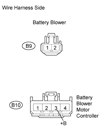 |
Disconnect the B9 battery blower connector.
Disconnect the B10 battery blower motor controller connector.
Measure the resistance of the wire harness side connectors.
| Tester Connection | Specified Condition |
| B9-2 - B10-3 (+B) | Below 1 Ω |
Reconnect the battery blower connector.
Reconnect the battery blower motor controller connector.
|
| ||||
| OK | |
|
| 8.CHECK WIRE HARNESS (BATTERY BLOWER - BATTERY ECU) |
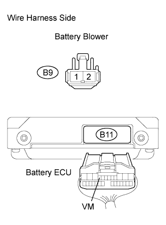 |
Disconnect the B9 battery blower connector.
Disconnect the B11 battery ECU connector.
Measure the resistance of the wire harness side connectors.
| Tester Connection | Specified Condition |
| B9-1 - B11-9 (VM) | Below 1 Ω |
| B9-1 or B11-9 (VM) - Body ground | 10 kΩ or higher |
Reconnect the battery blower connector.
Reconnect the battery ECU connector.
|
| ||||
| OK | |
|
| 9.CHECK WIRE HARNESS (BATTERY BLOWER - BATTERY BLOWER MOTOR CONTROLLER) |
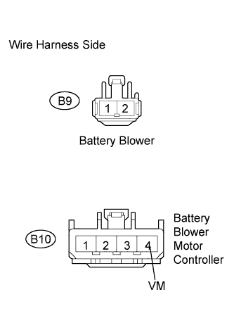 |
Disconnect the B9 battery blower connector.
Disconnect the B10 battery blower motor controller connector.
Measure the resistance of the wire harness side connectors.
| Tester Connection | Specified Condition |
| B9-1 - B10-4 (VM) | Below 1 Ω |
| B9-1 or B10-4 (VM) - Body ground | 10 kΩ or higher |
Reconnect the battery blower connector.
Reconnect the battery blower motor controller connector.
|
| ||||
| OK | |
|
| 10.CHECK WIRE HARNESS (NO. 1 BATTERY BLOWER RELAY - BATTERY ECU) |
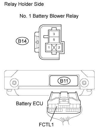 |
Remove the B14 No. 1 battery blower relay.
Disconnect the B11 battery ECU connector.
Measure the resistance of the wire harness side connectors.
| Tester Connection | Specified Condition |
| B14-2 - B11-10 (FCTL1) | Below 1 Ω |
| B14-2 or B11-10 (FCTL1) - Body ground | 10 kΩ or higher |
Reinstall the No. 1 battery blower relay.
Reconnect the battery ECU connector.
|
| ||||
| OK | |
|
| 11.CHECK WIRE HARNESS (BATTERY BLOWER MOTOR CONTROLLER - BATTERY ECU) |
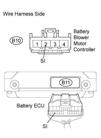 |
Disconnect the B10 battery blower motor controller connector.
Disconnect the B11 battery ECU connector.
Measure the resistance of the wire harness side connectors.
| Tester Connection | Specified Condition |
| B10-2 (SI) - B11-24 (SI) | Below 1 Ω |
| B10-2 (SI) or B11-24 (SI) - Body ground | 10 kΩ or higher |
Reconnect the battery blower motor controller connector.
Reconnect the battery ECU connector.
|
| ||||
| OK | |
|
| 12.CHECK WIRE HARNESS (BATTERY BLOWER MOTOR CONTROLLER - BODY GROUND) |
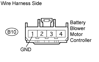 |
Disconnect the B10 battery blower motor controller connector.
Measure the resistance of the wire harness side connector.
| Tester Connection | Specified Condition |
| B10-1 (GND) - Body ground | Below 1 Ω |
Reconnect the battery blower motor controller connector.
|
| ||||
| OK | |
|
| 13.CHECK WIRE HARNESS (NO. 1 BATTERY BLOWER RELAY) |
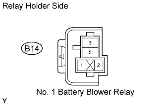 |
Remove the B14 No. 1 battery blower relay.
Measure the resistance of the wire harness side connectors.
| Tester Connection | Specified Condition |
| B14-1 - B14-3 | Below 1 Ω |
Reinstall the No. 1 battery blower relay.
|
| ||||
| OK | ||
 | ||
| ||
| 14.CHECK WIRE HARNESS (NO. 1 BATTERY BLOWER RELAY - BATT FAN FUSE) |
|
Remove the B14 No. 1 battery blower relay.
Remove the BATT FAN fuse from the engine room relay block.
Measure the resistance of the wire harness side connector.
| Tester Connection | Specified Condition |
| B14-3 or BATT FAN fuse terminal 2 - Body ground | 10 kΩ or higher |
Reinstall the No. 1 battery blower relay.
Reinstall the BATT FAN fuse.
|
| ||||
| OK | |
|
| 15.CHECK WIRE HARNESS (NO. 1 BATTERY BLOWER RELAY - BATTERY BLOWER) |
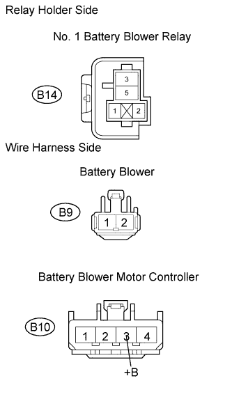 |
Remove the B14 No. 1 battery blower relay.
Disconnect the B9 battery blower connector.
Disconnect the B10 battery blower motor controller connector.
Measure the resistance of the wire harness side connector.
| Tester Connection | Specified Condition |
| B14-5, B9-2 or B10-3 (+B) - Body ground | 10 kΩ or higher |
Reinstall the No. 1 battery blower relay.
Reconnect the battery blower connector.
Reconnect the battery blower motor controller connector.
|
| ||||
| OK | |
|
| 16.CHECK WIRE HARNESS (NO. 1 BATTERY BLOWER RELAY - BATTERY ECU) |
|
Remove the B14 No. 1 battery blower relay.
Disconnect the B11 battery ECU connector.
Measure the resistance of the wire harness side connectors.
| Tester Connection | Specified Condition |
| B14-1, B14-3 or B11-10 (FCTL1) - Body ground | 10 kΩ or higher |
Reinstall the No. 1 battery blower relay.
Reconnect the battery ECU connector.
|
| ||||
| OK | |
|
| 17.CHECK BATTERY BLOWER MOTOR CONTROLLER |
Check the battery blower motor controller (Click here).
|
| ||||
| OK | ||
| ||
| ||

