Home › BRAKE › BRAKE CONTROL › ELECTRONICALLY CONTROLLED BRAKE SYSTEM

DTC    C1241/41    Low Battery Positive Voltage or Abnormally High Battery Positive Voltage

DTC    C1242/42    Open in IG1 / IG2 Power Source Circuit

for Preparation Click here


DESCRIPTION

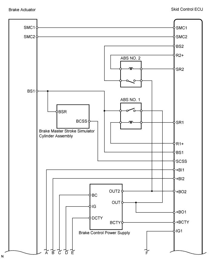
These codes are memorized when the power source voltage for the skid control ECU drops or the voltage for the ABS NO. 1, ABS NO. 2 relay operation drops.
Codes may be memorized when the voltage of the auxiliary battery temporarily drops.
When the power source voltage is too high, the skid control ECU stops functioning and outputs no DTCs, and the ABS and BRAKE warning light remain on.

HINT:
DTC C1256/56 (accumulator low voltage malfunction) may be memorized if the power source voltage drops.


DTC No.
Detailed Code
DTC Detection Condition
Trouble Area
C1241/41
81
System 1 is under the following conditions when READY is on:
  1. Linear solenoid cannot receive enough current (brake is applied).
  2. BS voltage is less than 8.9 V for at least 3 sec. (brake is not applied).
  3. 12 V-power source voltage inside ECU is less than 8.5 V when main relay is opened or VCM voltage is less than 4.7 V or 5 V or more for at least 0.05 sec.
  1. ABS NO. 1 relay
  2. Harness and connector
  3. Skid control power supply circuit
  4. Brake control power supply assembly
  5. Hybrid control system
C1241/41
82
System 2 is under the following conditions when READY is on:
  1. Linear solenoid cannot receive enough current (brake is applied).
  2. BS voltage is less than 8.9 V for at least 3 sec. (brake is not applied).
  3. 12 V-power source voltage inside ECU is less than 8.5 V when main relay is opened or VCM voltage is less than 4.7 V or 5.3 V or more for at least 0.05 sec.
  1. ABS NO. 2 relay
  2. Harness and connector
  3. Skid control power supply circuit
  4. Brake control power supply assembly
  5. Hybrid control system
C1241/41
83
Capacitor mode signal is received from brake control power supply for 3 sec. or more when READY is on.
  1. Brake control power supply assembly
  2. Brake control power supply
  3. Hybrid control system
C1241/41
84
ABS is requested to operate when the power source voltage of the main relay system is dropping.
  1. ABS NO. 1 relay
  2. ABS NO. 2 relay
  3. Harness and connector
C1242/42
87
Voltage is applied to IG2 terminal, but not applied to IG1 terminal for at least 4 sec.
  1. ABS NO. 1 relay
  2. Harness and connector
  3. Skid control power supply circuit
  4. Brake control power supply assembly
  5. Hybrid control system
C1242/42
88
Voltage is applied to IG1 terminal, but not applied to IG2 terminal for at least 4 sec.
  1. ABS NO. 2 relay
  2. Harness and connector
  3. Skid control power supply circuit
  4. Brake control power supply assembly
  5. Hybrid control system

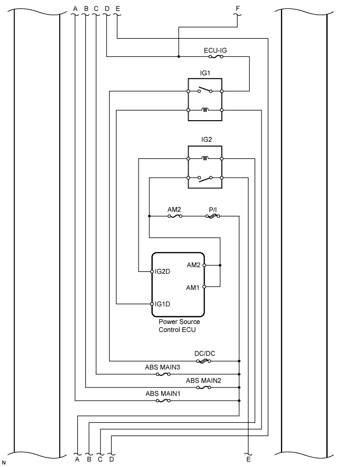
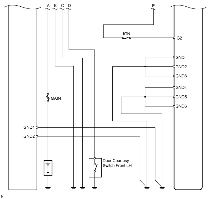
WIRING DIAGRAM


C126249E02


C153495E01


C126251E02


INSPECTION PROCEDURE

1.CHECK DTC (HYBRID CONTROL SYSTEM)
  1. Check that hybrid control system DTCs are output.
    Result 
    Result
    Proceed to
    DTC is not output
    A
    DTC is output
    B


B
REPAIR HYBRID CONTROL SYSTEM
A


2.CHECK AUXILIARY BATTERY VOLTAGE
  1. Check the auxiliary battery voltage.

    Standard voltage:
    10 to 14 V


NG
CHARGE OR REPLACE AUXILIARY BATTERY
OK


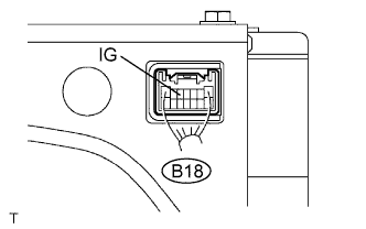
3.CHECK BRAKE CONTROL POWER SUPPLY (IG VOLTAGE)


    F047500E01
  1. Measure the voltage of the connector.

    Standard voltage:
    Tester Connection
    Condition
    Specified Condition
    B18-5 (IG) - Body ground
    Power switch ON (READY)
    10 to 14 V


NG
REPLACE BRAKE CONTROL POWER SUPPLY
OK


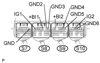
4.CHECK SKID CONTROL ECU


    F047485E73
  1. Measure the voltage of the connectors.

    HINT:
    Measure the voltage from behind the connector with the connector connected to the skid control ECU.

    Standard voltage:
    Tester Connection
    Condition
    Specified Condition
    S8-7 (IG1) - Body ground
    Power switch ON (READY)
    10 to 14 V
    S10-5 (IG2) - Body ground
    Power switch ON (READY)
    10 to 14 V
    S8-3 (+BI1) - Body ground
    Always
    10 to 14 V
    S9-5 (+BI2) - Body ground
    Always
    10 to 14 V

  1. Measure the resistance of the connectors.

    Standard resistance:
    Tester Connection
    Specified Condition
    S7-1 (GND) - Body ground
    Below 1 Ω
    S8-2 (GND2) - Body ground
    Below 1 Ω
    S8-1 (GND3) - Body ground
    Below 1 Ω
    S9-2 (GND4) - Body ground
    Below 1 Ω
    S9-1 (GND5) - Body ground
    Below 1 Ω
    S10-4 (GND6) - Body ground
    Below 1 Ω


NG
REPAIR OR REPLACE HARNESS AND CONNECTOR
OK


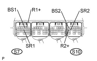
5.CHECK SKID CONTROL ECU (BS1, R1+, SR1, BS2, R2+, SR2 VOLTAGE)


    F047485E74
  1. Measure the voltage of the connectors.

    HINT:
    Measure the voltage from behind the connector with the connector connected to the skid control ECU.

    Standard voltage:
    Tester Connection
    Condition
    Specified Condition
    S7-2 (R1+) - Body ground
    Power switch ON (READY)
    8 to 13 V
    S10-17 (R2+) - Body ground
    Power switch ON (READY)
    8 to 13 V
    S7-12 (SR1) - Body ground
    Power switch ON (READY)
    Below 1.5 V
    S10-15 (SR2) - Body ground
    Power switch ON (READY)
    Below 1.5 V
    S7-3 (BS1) - Body ground
    Power switch ON (READY)
    10 to 14 V
    S10-7 (BS2) - Body ground
    Power switch ON (READY)
    10 to 14 V

    Result 
    Result
    Proceed to
    All OK
    A
    NG (R1+, R2+)
    B
    NG (SR1, SR2, BS1, BS2)
    C


B
REPLACE SKID CONTROL ECU

C
REPAIR OR REPLACE HARNESS AND CONNECTOR
A


6.RECONFIRM DTC
  1. Clear the DTCs (Click here ).

  1. Turn the power switch ON (READY).

  1. Check the same DTCs are recorded (Click here).
    Result 
    Result
    Proceed to
    DTC is not output
    A
    DTC is output
    B


B
REPLACE SKID CONTROL ECU
A

END (DTC MAY BE STORED DUE TO TEMPORARY POWER SOURCE VOLTAGE DROP)