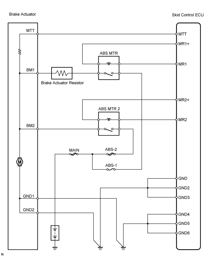
DTC C1252/52 Brake Booster Pump Motor on Time Abnormally Long |
DTC C1253/53 Pump Motor Relay Malfunction |
| DTC No. | INF Code | DTC Detection Condition | Trouble Area |
| C1252/52 | 130 | Motor relay is ON for at least 5 min. | Brake actuator assembly |
| C1253/53 | 132 | Motor relay 1 coil (monitor) is energized for at least 1 sec. when main relay 1 monitor (BS1) is 9.5 V or more and motor relay 1 is off. |
|
| C1253/53 | 133 | Motor relay 1 coil (monitor) is not energized for at least 1 sec. when main relay 1 monitor (BS1) is 9.5 V or more and motor relay 1 is on. |
|
| C1253/53 | 134 | MTT input is 3.5 V or less for at least 0.2 sec. when main relay 1 monitor (BS1) is 9.5 V or more and motor relay 1 is on. |
|
| C1253/53 | 136 | Motor relay 2 coil (monitor) is energized for at least 1 sec. when main relay 2 monitor (BS2) is 9.5 V or more and motor relay 2 is off. |
|
| C1253/53 | 137 | Motor relay 2 coil (monitor) is not energized for at least 1 sec. (0.2 sec. during initial check) when main relay 2 monitor (BS2) is 9.5 V or more and motor relay 2 is on. |
|
| C1253/53 | 138 | MTT input is 3.5 V or less for at least 1 sec. (0.2 sec. during initial check) when main relay 1 monitor (BS1) is 9.5 V or more and motor relay 2 is on. |
|
| C1253/53 | 140 | MTT input is 3.5 V or more for at least 2 sec. when motor relay 1 and 2 are off. |
|
| 1.PERFORM ACTIVE TEST BY TECHSTREAM (ABS MOTOR RELAY OPERATION) |
Select the Active Test, generate a control command, and then check that the ABS motor relay operates.
| Tester Display | Test Part | Control Range | Diagnostic Note |
| Motor Relay 1 | Motor relay 1 | Relay ON / OFF | Operation of solenoid (clicking sound) can be heard |
| Motor Relay 2 | Motor relay 2 | Relay ON / OFF | Operation of solenoid (clicking sound) can be heard |
|
| ||||
| OK | |
 |
| 2.INSPECT FUSE (ABS-1, ABS-2) |
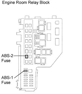 |
Remove the ABS-1 and ABS-2 fuses from the engine room relay block.
Measure the resistance of the fuses.
|
| ||||
| OK | |
|
| 3.INSPECT BRAKE ACTUATOR ASSEMBLY |
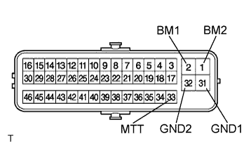 |
Disconnect the brake actuator connector.
Measure the resistance of the actuator.
| Tester Connection | Specified Condition |
| A2-1 (BM2) - A2-31 (GND1) | Below 10 Ω |
| A2-2 (BM1) - A2-31 (GND1) | Below 10 Ω |
| A2-1 (BM2) - A2-2 (BM1) | Below 1 Ω |
| A2-31 (GND1) - A2-32 (GND2) | Below 1 Ω |
| A2-1 (BM2) - A2-33 (MTT) | About 33 Ω |
| A2-2 (BM1) - A2-33 (MTT) | About 33 Ω |
|
| ||||
| OK | |
|
| 4.CHECK WIRE HARNESS (SKID CONTROL ECU - BRAKE ACTUATOR ASSEMBLY) |
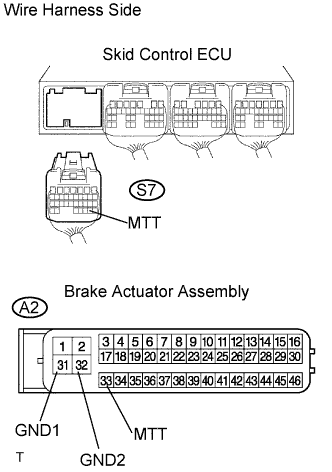 |
Disconnect the S7 ECU connector.
Disconnect the A2 actuator connector.
Measure the resistance of the wire harness side connectors.
| Tester Connection | Specified Condition |
| S7-29 (MTT) - A2-33 (MTT) | Below 1 Ω |
| A2-31 (GND1) - Body ground | Below 1 Ω |
| A2-32 (GND2) - Body ground | Below 1 Ω |
|
| ||||
| OK | |
|
| 5.READ VALUE OF TECHSTREAM (ACCUMULATOR PRESSURE SENSOR) |
Check the Data List for proper functioning of the accumulator pressure sensor.
Depress the brake pedal 4 or 5 times to operate the pump motor, and check the output value on Techstream with the motor stopped (not braking).
| Tester Display | Measurement Item/Range | Normal Condition | Diagnostic Note |
| Accumulator Sensor 1 | Accumulator pressure sensor 1 / Min.: 0 V, Max.: 5 V | Specified value: 3.2 to 4.0 V | - |
|
| ||||
| OK | ||
 | ||
| ||
| 6.INSPECT RELAY (Marking: ABS MTR, ABS MTR 2) |
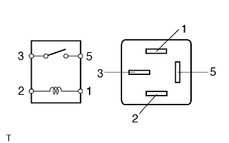 |
Remove the ABS MTR and ABS MTR 2 relays from the engine room relay block.
Measure the resistance of the relays.
| Tester Connection | Specified Condition |
| 3 - 5 | 10 kΩ or higher |
| 3 - 5 | Below 1 Ω (when battery voltage is applied to terminals 1 and 2) |
|
| ||||
| OK | |
|
| 7.CHECK WIRE HARNESS (ENGINE ROOM RELAY BLOCK - BATTERY) |
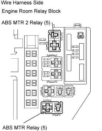 |
Remove the ABS MTR and MTR 2 relays from the engine room relay block.
Measure the voltage of the wire harness side connectors.
| Tester Connection | Specified Condition |
| ABS MTR relay terminal 5 - Body ground | 10 to 14 V |
| ABS MTR 2 relay terminal 5 - Body ground | 10 to 14 V |
|
| ||||
| OK | |
|
| 8.CHECK WIRE HARNESS (ENGINE ROOM RELAY BLOCK - BRAKE ACTUATOR) |
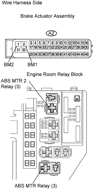 |
Disconnect the A2 actuator connector.
Remove the ABS MTR and ABS MTR 2 relays from the engine room relay block.
Measure the resistance of the wire harness side connectors.
| Tester Connection | Specified Condition |
| A2-1 (BM2) - ABS MTR 2 relay terminal 3 | Below 1 Ω |
| A2-2 (BM1) - ABS MTR relay terminal 3 | Below 1 Ω |
| A2-1 (BM2) - Body ground | 10 kΩ or higher |
| A2-2 (BM1) - Body ground | 10 kΩ or higher |
|
| ||||
| OK | |
|
| 9.CHECK WIRE HARNESS (ENGINE ROOM RELAY BLOCK - SKID CONTROL ECU) |
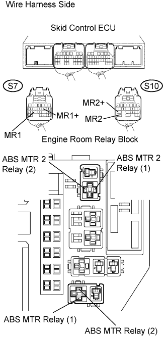 |
Disconnect the S7 and S10 ECU connectors.
Remove the ABS MTR and MTR 2 relays from the engine room relay block.
Measure the resistance of the wire harness side connectors.
| Tester Connection | Specified Condition |
| S7-11 (MR1+) - ABS MTR relay terminal 2 | Below 1 Ω |
| S7-25 (MR1) - ABS MTR relay terminal 1 | Below 1 Ω |
| S10-25 (MR2+) - ABS MTR 2 relay terminal 2 | Below 1 Ω |
| S10-30 (MR2) - ABS MTR 2 relay terminal 1 | Below 1 Ω |
| S7-11 (MR1+) - Body ground | 10 kΩ or higher |
| S7-25 (MR1) - Body ground | 10 kΩ or higher |
| S10-25 (MR2+) - Body ground | 10 kΩ or higher |
| S10-30 (MR2) - Body ground | 10 kΩ or higher |
|
| ||||
| OK | ||
| ||
| ||

