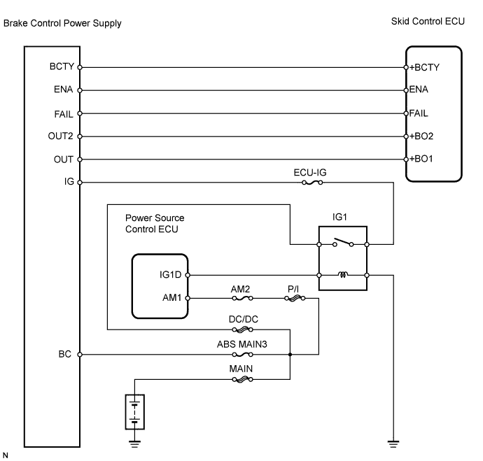
DTC C1378/44 Capacitor Communication Malfunction |
| DTC No. | INF Code | DTC Detection Condition | Trouble Area |
| C1378/44 | 112 | When either condition below is met:
|
|
| C1377/43 | 113 | When either condition below is met:
|
|
| 1.CHECK BRAKE CONTROL POWER SUPPLY (IG VOLTAGE) |
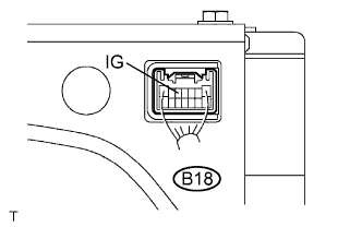 |
Measure the voltage of the connector.
| Tester Connection | Condition | Specified Condition |
| B18-5 (IG) - Body ground | Power switch ON (READY) | 10 to 14 V |
|
| ||||
| OK | |
 |
| 2.CHECK WIRE HARNESS (SKID CONTROL ECU - BRAKE CONTROL POWER SUPPLY) |
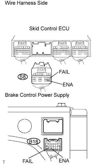 |
Disconnect the S8 ECU connector.
Disconnect the B18 supply connector.
Measure the resistance of the wire harness side connectors.
| Tester Connection | Specified Condition |
| S8-30 (ENA) - B18-12 (ENA) | Below 1 Ω |
| S8-20 (FAIL) - B18-13 (FAIL) | Below 1 Ω |
| S8-30 (ENA) - Body ground | 10 kΩ or higher |
| S8-20 (FAIL) - Body ground | 10 kΩ or higher |
|
| ||||
| OK | |
|
| 3.CHECK SKID CONTROL ECU (ENA, FAIL VOLTAGE) |
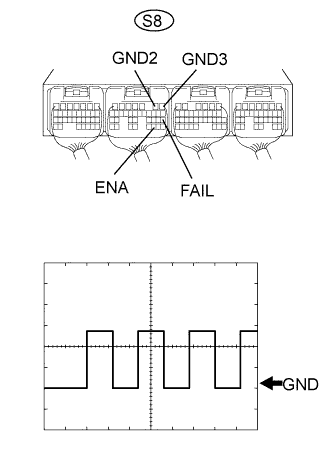 |
Using an oscilloscope, check the waveform of the skid control ECU.
| Item | Content |
| Symbols (terminal No.) | S8-20 (FAIL) - S8-1, 2 (GND3, 2) |
| Tool Setting | 5 V/DIV/., 200 ms/DIV. |
| Condition | Condition READY is displayed on the meter |
| Item | Content |
| Symbols (terminal No.) | S8-30 (ENA) - S8-1, 2 (GND3, 2) |
| Tool Setting | 5 V/DIV/., 100 ms/DIV. |
| Condition | Condition READY is displayed on the meter |
| Result | Proceed to |
| A | Both waveforms are normal |
| B | Waveform (ENA) is abnormal |
| C | Waveform (FAIL) is abnormal |
|
| ||||
|
| ||||
| A | ||
 | ||
| ||
