Install the 3 screws.
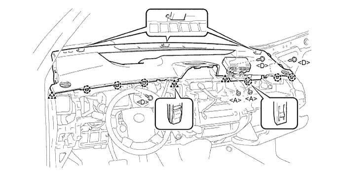
INSTRUMENT PANEL SAFETY PAD > INSTALLATION |
| 1. INSTALL INSTRUMENT PANEL SAFETY PAD |
Attach the 6 claws and 3 clips to install the instrument panel.
Install the 2 bolts.
Install the 3 screws.
| 2. CONNECT PASSENGER AIRBAG CONNECTOR |
| 3. INSTALL FRONT PILLAR GARNISH LH |
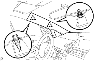 |
w/o Curtain Shield Airbag:
Attach the 2 clips to install the pillar garnish.
w/ Curtain Shield Airbag:
Remove the protective cover.
w/ Curtain Shield Airbag:
Install the pillar garnish.
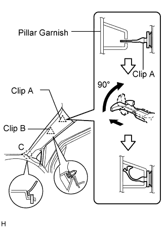 |
Set the claws of the pillar garnish to the area labeled C.
Insert the tip of clip A into the pillar garnish's hole.
Using needle-nose pliers, rotate the tip of clip A 90°. Then push the pillar garnish toward the vehicle body to attach the base of clip A and clip B.
| 4. INSTALL FRONT PILLAR GARNISH RH |
| 5. INSTALL FRONT PILLAR GARNISH CORNER PIECE LH |
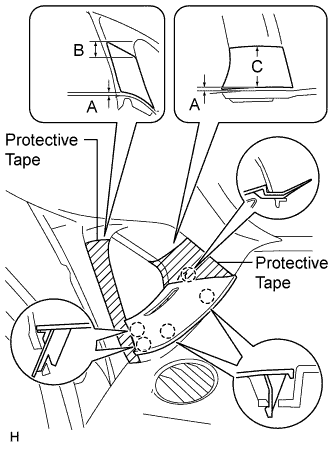 |
Put protective tape as shown in the illustration.
| Area | Specified Condition |
| A | 2.0 mm (0.079 in.) |
| B | 10.0 mm (0.394 in.) |
| C | 50.0 mm (1.969 in.) |
Attach the 5 claws to install the corner piece.
| 6. INSTALL FRONT PILLAR GARNISH CORNER PIECE RH |
| 7. INSTALL NO. 1 INSTRUMENT PANEL SPEAKER PANEL SUB-ASSEMBLY (w/ JBL Sound System) |
| 8. INSTALL GLOVE COMPARTMENT DOOR |
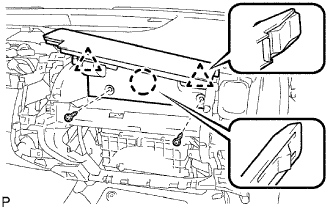 |
Attach the claw and 2 clips to install the glove compartment door.
Install the 2 screws.
| 9. INSTALL INSTRUMENT PANEL HOLE COVER |
Install the 2 instrument panel hole covers.
| 10. INSTALL INSTRUMENT CLUSTER FINISH PANEL END |
| 11. INSTALL INSTRUMENT PANEL CUSHION |
| 12. INSTALL GLOVE COMPARTMENT DOOR ASSEMBLY |
Attach the 2 hinges to install the door.
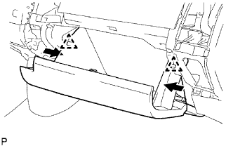 |
While pushing in the sides of the glove compartment door as indicated by the arrows in the illustration, engage it to the 2 stoppers.
| 13. INSTALL GLOVE COMPARTMENT DOOR STOPPER SUB-ASSEMBLY |
| 14. INSTALL MULTI-DISPLAY ASSEMBLY |
| 15. INSTALL NO. 2 INSTRUMENT PANEL REGISTER ASSEMBLY |
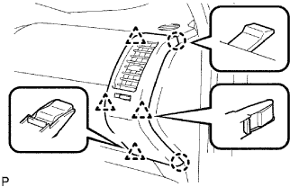 |
Attach the 2 claws and 4 clips to install the instrument panel register.
| 16. INSTALL NO. 4 INSTRUMENT PANEL REGISTER ASSEMBLY |
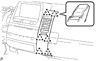 |
Attach the 6 clips to install the instrument panel register.
| 17. INSTALL NO. 3 INSTRUMENT PANEL REGISTER ASSEMBLY |
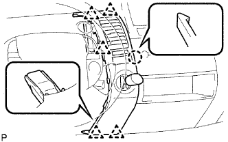 |
Connect the connector.
Attach the claw and 5 clips to install the instrument panel register.
| 18. INSTALL UPPER INSTRUMENT PANEL FINISH PANEL SUB-ASSEMBLY |
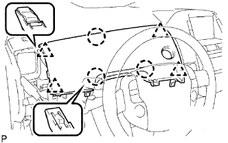 |
Connect the connector.
Attach the 3 claws and 4 clips to install the instrument panel finish panel.
| 19. INSTALL LOWER INSTRUMENT PANEL FINISH PANEL SUB-ASSEMBLY |
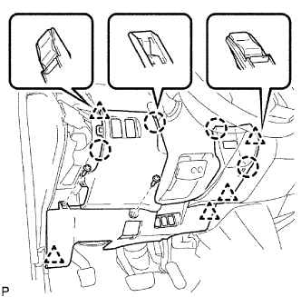 |
Connect the connectors.
Attach the 4 claws and 5 clips to install the instrument panel finish panel.
Connect the hood lock control cable.
Install the 2 screws.
| 20. INSTALL NO. 1 INSTRUMENT PANEL REGISTER ASSEMBLY |
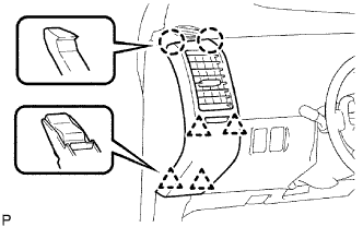 |
Attach the 2 claws and 4 clips to install the instrument panel register.
| 21. CONNECT CABLE TO NEGATIVE BATTERY TERMINAL |
| 22. PERFORM INITIALIZATION |
Perform initialization (Click here).
| 23. CHECK SRS WARNING LIGHT |
Check the SRS warning light (Click here).