Home › ENGINE › 1NZ-FXE ENGINE CONTROL SYSTEM › SFI SYSTEM

DTC    P0111    Intake Air Temperature Sensor Gradient Too High

for Preparation Click here


DESCRIPTION

A067628E28
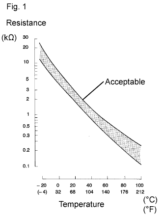
  1. The Intake Air Temperature (IAT) sensor, in the Mass Air Flow (MAF) meter, monitors the IAT. The IAT sensor has a built-in thermistor with a resistance that varies according to the temperature of the intake air. When the IAT is low, the resistance of the thermistor increases. When the temperature is high, the resistance drops. These variations in resistance are transmitted to the ECM (included in the hybrid vehicle control ECU) as voltage changes (See Fig. 1).
  2. The IAT sensor is powered by a 5 V supply from the THA terminal of the ECM, via resistor R.
  3. Resistor R and the IAT sensor are connected in series. When the resistance value of the IAT sensor changes, the voltage at terminal THA also varies according to changes in the IAT. Based on this signal, the ECM increases the fuel injection volume when the engine is cold to improve driveability.

DTC No.
DTC Detection Condition
Trouble Area
P0111
When either of following conditions are met (2 trip detection logic):
  1. In duration between engine warmed up and next engine starts, change in Intake Air Temperature (IAT) sensor output bellow threshold
  2. During engine warming up after cold engine starts, change in IAT sensor output bellow threshold
Mass air flow meter

MONITOR DESCRIPTION

  1. After the warm engine is stopped
    The ECM (included in the hybrid vehicle control ECU) monitors the intake air temperature variation in the period from when the engine was warmed up on the previous trip until the next engine start. If the change in engine coolant temperature sensor output is less than the threshold, it is determined that a malfunction has occurred in the intake air temperature sensor. When this is detected, the MIL is illuminated and the DTC is set.
  1. After a cold engine is started
    The monitor runs when the engine is started cold after 5 hours or more have elapsed since the engine stopped. If the intake air temperature sensor output variation while the engine is warming up is less than the threshold, it is determined that a malfunction has occurred in the intake air temperature sensor. When this is detected in 2 consecutive driving cycles, the MIL is illuminated and the DTC is set.

MONITOR STRATEGY


Related DTCs
P0111: Intake air temperature sensor rationality (After engine stop)
P0111: Intake air temperature sensor rationality (After cold engine start)
Required Sensors/Components (Main)
Intake Air Temperature (IAT) sensor
Required Sensors/Components (Related)
-
Frequency of Operation
Once per driving cycle
Duration
5 hours or more
MIL Operation
2 driving cycles
Sequence of Operation
None

TYPICAL ENABLING CONDITIONS


All: 
Monitor will not run if the following DTCs are present
None

After engine stop: 
Time after engine start
10 seconds or more
Battery voltage
10.5 V or more
ECT sensor circuit
OK
ECT before engine stop
70°C (158°F) or more
Accumulated MAF amount before engine stop
2000 g or more
Key-off duration
30 minutes

After cold engine start: 
Key-off duration
5 hours
Time after engine start
10 seconds or more
ECT sensor circuit
OK
ECT
70°C (158°F) or more
Accumulated MAF amount
2000 g or more
Either of the following conditions 1 or 2 is met:
-
1. Duration while engine load is low
120 seconds or more
2. Duration while engine load is high
10 seconds or more

TYPICAL MALFUNCTION THRESHOLDS


After engine stop: 
IAT change
Less than 1°C (2°F)

After cold engine start: 
IAT change
Less than 1°C (2°F)

WIRING DIAGRAM

Refer to DTC P0110 .

INSPECTION PROCEDURE

1.CHECK ANY OTHER DTCS OUTPUT (IN ADDITION TO DTC P0111)
  1. Connect Techstream to the DLC3.

  1. Turn the power switch ON (IG).

  1. Turn the tester on.

  1. Select the following menu items: Powertrain / Engine and ECT / Trouble Codes.

  1. Read DTCs.

    Result:
    Result
    Proceed to
    P0111 and other DTCs
    A
    P0111
    B

    HINT:
    If any DTCs other than P0111 are output, troubleshoot those DTCs first.


B
REPLACE MASS AIR FLOW METER (Click here)
A

GO TO DTC CHART (Click here)