 |
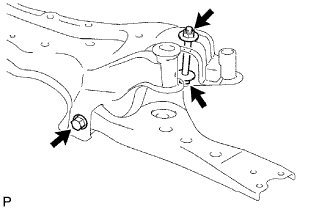
Install the front suspension lower No. 1 arm to the suspension crossmember and temporarily tighten the front suspension lower No. 1 arm with the 2 bolts and nut.
FRONT SUSPENSION LOWER NO. 1 ARM > INSTALLATION |
| 1. TEMPORARILY TIGHTEN FRONT SUSPENSION LOWER NO. 1 ARM SUB-ASSEMBLY LH |
|
Install the front suspension lower No. 1 arm to the suspension crossmember and temporarily tighten the front suspension lower No. 1 arm with the 2 bolts and nut.
| 2. CONNECT FRONT SUSPENSION CROSSMEMBER SUB-ASSEMBLY |
| 3. INSTALL FRONT DRIVE SHAFT ASSEMBLY LH |
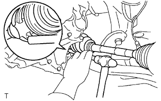 |
Apply ATF to the spline of the inboard joint.
Align the spline of the front drive shaft and insert the front drive shaft using a brass bar and hammer.
Install the front fender apron seal.
| 4. INSTALL FRONT DRIVE SHAFT ASSEMBLY RH |
| 5. INSTALL FRONT AXLE ASSEMBLY LH |
Install the axle hub and dust cover with the 4 bolts.
| 6. INSTALL FRONT AXLE ASSEMBLY RH |
| 7. INSTALL FRONT SUSPENSION LOWER NO. 1 ARM SUB-ASSEMBLY LH |
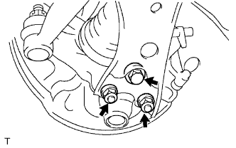 |
Install the front suspension lower No. 1 arm to the front lower ball joint with the bolt and 2 nuts.
| 8. INSTALL FRONT SUSPENSION LOWER NO. 1 ARM SUB-ASSEMBLY RH |
| 9. INSTALL FRONT STABILIZER LINK ASSEMBLY |
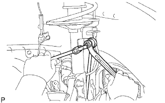 |
Connect the front stabilizer link LH and RH to the front shock absorber with coil spring with the nuts.
| 10. INSTALL NO. 2 TIE ROD END SUB-ASSEMBLY |
| 11. INSTALL NO. 1 TIE ROD END SUB-ASSEMBLY |
| 12. INSTALL FRONT AXLE HUB NUT LH |
Using a chisel and hammer, stake the hub nut.
| 13. INSTALL FRONT AXLE HUB NUT RH |
| 14. INSTALL FRONT WHEEL |
| 15. INSTALL FRONT EXHAUST PIPE ASSEMBLY |
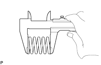 |
Using a vernier caliper, measure the free length of the compression spring.
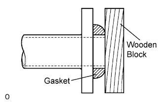 |
Using a plastic-faced hammer and wooden block, tap in a new gasket until its surface is flush with the exhaust manifold.
Connect the 2 exhaust pipe supports, and install the exhaust pipe.
Install the 2 compression springs and 2 bolts.
| 16. STABILIZE SUSPENSION |
Lower the vehicle and bounce it up and down several times to stabilize the front suspension.
| 17. CONNECT STEERING SLIDING YOKE SUB-ASSEMBLY |
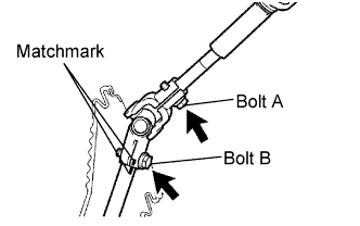 |
Align the matchmarks and install the sliding yoke to the intermediate shaft with the bolt labeled B.
Tighten the bolt labeled A.
| 18. INSTALL COLUMN HOLE COVER SILENCER SHEET |
| 19. FULLY TIGHTEN FRONT SUSPENSION LOWER NO. 1 ARM SUB-ASSEMBLY LH |
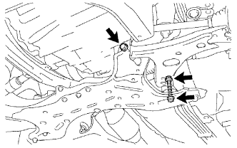 |
Fully tighten the 2 bolts.
| 20. INSPECT AND ADJUST FRONT WHEEL ALIGNMENT |
Inspect and adjust the front wheel alignment (Click here).