 |
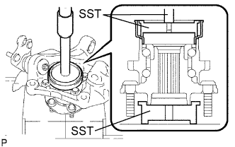
Using SST and a press, press in a new dust deflector.
- SST
- 09950-70010
(09951-07150)
09608-32010
09950-60020 (09951-00720)
- NOTICE:
- Align the dust deflector hole and the steering knuckle hole.
FRONT LOWER BALL JOINT > INSTALLATION |
| 1. INSTALL FRONT LOWER BALL JOINT ASSEMBLY |
Install the lower ball joint front LH to the steering knuckle with the castle nuts.
Install a new clip to the steering knuckle.
| 2. INSTALL FRONT NO. 1 WHEEL BEARING DUST DEFLECTOR LH |
|
Using SST and a press, press in a new dust deflector.
| 3. INSTALL FRONT AXLE ASSEMBLY LH |
Install the axle hub and dust cover with the 4 bolts.
| 4. CONNECT FRONT SUSPENSION LOWER NO. 1 ARM SUB-ASSEMBLY LH |
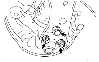 |
Lower the front suspension lower No. 1 arm and install the lower ball joint front to the front suspension lower No. 1 arm with the bolt and 2 nuts.
| 5. CONNECT NO. 2 TIE ROD END SUB-ASSEMBLY |
| 6. INSTALL FRONT DISC |
Align matchmarks on the disc and the axle hub. Install the front disc.
| 7. CONNECT FRONT DISC BRAKE CALIPER ASSEMBLY LH |
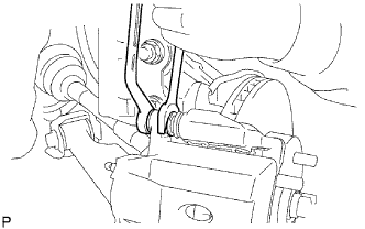 |
Install the front disc brake cylinder with the 2 bolts.
Placing a new gasket inbetween, connect the No. 1 flexible hose to the front disc brake cylinder with the union bolt.
| 8. INSTALL FRONT SPEED SENSOR LH |
Clean the connecting portion of the sensor.
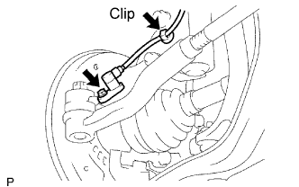 |
Install the sensor with the bolt.
Install the clip to the front shock absorber.
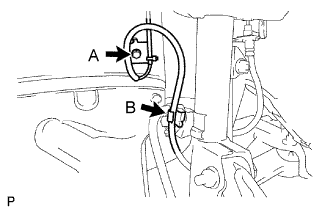 |
Install the sensor clamps to the body and front shock absorber with the bolts A and B.
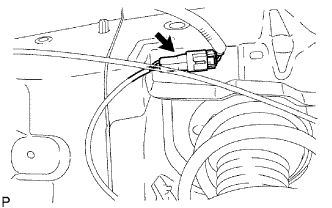 |
Connect the sensor connector.
| 9. INSTALL FRONT AXLE HUB NUT LH |
Using a chisel and hammer, stake the hub nut.
| 10. INSTALL FRONT WHEEL |
| 11. INSPECT AND ADJUST FRONT WHEEL ALIGNMENT |
Inspect and adjust the front wheel alignment (Click here).
| 12. CHECK SPEED SENSOR SIGNAL |
Check the speed sensor signal (Click here).