 |
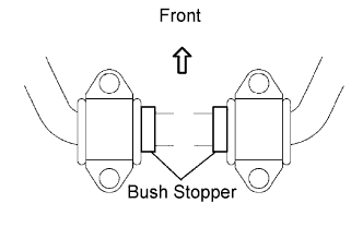
Install the bush to the outer side of the bush stopper on the stabilizer bar.
- NOTICE:
- Place the cutout of the stabilizer bush facing the rear side.
- Ensure the right and left deviation of the stabilizer bar is 5 mm (0.20 in.) or less.
FRONT STABILIZER BAR > INSTALLATION |
| 1. INSTALL FRONT STABILIZER BAR |
Insert the front stabilizer bar from the right side of the vehicle.
| 2. INSTALL FRONT NO. 1 STABILIZER BAR BUSH |
|
Install the bush to the outer side of the bush stopper on the stabilizer bar.
| 3. INSTALL STEERING GEAR ASSEMBLY |
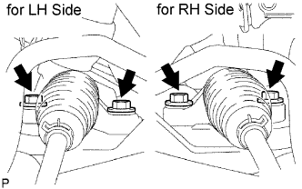 |
Install the steering gear from the left side of the vehicle.
Install the No. 1 column hole cover to the steering gear.
Install the steering gear to the crossmember with the 4 bolts.
| 4. INSTALL NO. 1 STEERING COLUMN HOLE COVER SUB-ASSEMBLY |
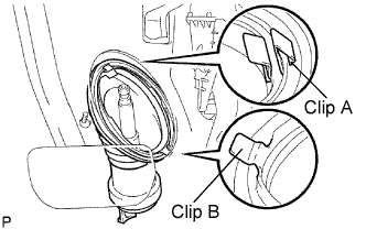 |
Install the clip labeled B to the vehicle body and install the No. 1 column hole cover to the vehicle body with the clip labeled A.
| 5. INSTALL STEERING INTERMEDIATE SHAFT |
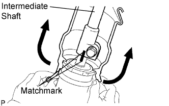 |
Move the No. 1 column hole cover to the upper side of the vehicle, align the matchmarks, and install the intermediate shaft from the inside of the vehicle.
Install the bolt.
Fit the recessed part on the No. 1 column hole cover to the steering gear.
| 6. CONNECT FRONT NO. 1 STABILIZER BRACKET LH |
Install the No. 1 stabilizer bracket the front suspension crossmember with the 2 bolts.
| 7. CONNECT FRONT NO. 1 STABILIZER BRACKET RH |
| 8. INSTALL FRONT EXHAUST PIPE ASSEMBLY |
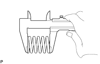 |
Using a vernier caliper, measure the free length of the compression spring.
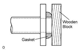 |
Using a plastic-faced hammer and wooden block, tap in a new gasket until its surface is flush with the exhaust manifold.
Connect the 2 exhaust pipe supports, and install the exhaust pipe.
Install the 2 compression springs and 2 bolts.
| 9. INSTALL FLOOR PANEL BRACE FRONT |
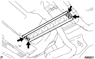 |
Install the floor panel brace with the 2 bolts.
| 10. INSTALL FRONT STABILIZER LINK ASSEMBLY LH |
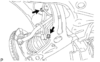 |
Install the front stabilizer link LH with the 2 nuts.
| 11. INSTALL NO. 2 TIE ROD END SUB-ASSEMBLY |
| 12. INSTALL NO. 1 TIE ROD END SUB-ASSEMBLY |
Connect the tie rod end to the steering knuckle and install it with the castle nut.
Install a new clip.
| 13. INSTALL FRONT WHEEL |
| 14. INSPECT AND ADJUST FRONT WHEEL ALIGNMENT |
Inspect and adjust the front wheel alignment (Click here).