 |
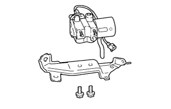
Install the 2 stud bolts to the brake stroke simulator cylinder.
- Torque:
- 5.0 N*m{ 51 kgf*cm , 44 in.*lbf }
BRAKE STROKE SIMULATOR CYLINDER > INSTALLATION |
| 1. INSTALL BRAKE STROKE SIMULATOR CYLINDER SUB-ASSEMBLY |
|
Install the 2 stud bolts to the brake stroke simulator cylinder.
Install the brake stroke simulator cylinder to the bracket with the 2 bolts.
Install the connector clamp of the brake stroke simulator cylinder to the bracket.
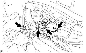 |
Install the brake stroke simulator cylinder with bracket to the body with the 2 nuts and 2 bolts.
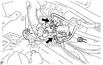 |
Using SST, connect the 2 brake tubes to the brake stroke simulator cylinder.
Connect the connector.
| 2. INSTALL OUTER FRONT COWL TOP PANEL SUB-ASSEMBLY |
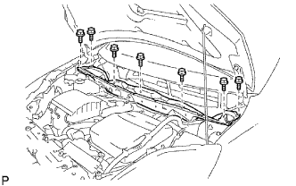 |
Install the outer front cowl top panel with the 7 bolts.
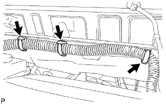 |
Install the 3 clamps to the outer front cowl top panel.
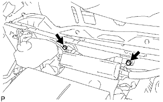 |
Install the engine room No. 2 R/B with the 2 bolts.
| 3. INSTALL WINDSHIELD WIPER MOTOR AND LINK ASSEMBLY |
Install the windshield wiper motor and link (Click here).
| 4. FILL RESERVOIR WITH BRAKE FLUID |
Add brake fluid into the reservoir.
| 5. BLEED AIR FROM MASTER CYLINDER/STROKE SIMULATOR |
Remove the No. 1 and No. 2 motor relays.
Bleed the air out of the FR/FL wheels in accordance with the display.
Install the No. 1 and No. 2 motor relays.
Bleed the air out of the stroke simulator line.
Depress the brake pedal 20 times in 20 seconds.
Perform the usual air bleeding for the FL wheel.
The air bleeding of the master cylinder/stroke simulator finishes if the display appears.
| 6. INSPECT FOR BRAKE FLUID LEAK |
| 7. CHECK FLUID LEVEL IN RESERVOIR |
| 8. CHECK AND CLEAR DTC |
Check and clear the DTC (Click here).
| 9. CHECK OPERATION |
Check battery voltage.
Connect the Techstream and pedal effort gauge.
Connect the pedal effort gauge.
Move the shift lever to the P position. Apply the parking brake and connect the Techstream to the DLC3.
Turn the power switch ON (IG).
Clear the DTC (Click here).
Check operation w/o brake booster.
Check and adjust brake pedal height .
Check pedal free play .
Check pedal reserve distance .
Turn on the Techstream and enter the following menus: Chassis / ABS/VSC/TRAC / Utility / Electronically Controlled Brake system Utility / Electronically Controlled Brake system Invalid to prohibit the brake control.
Enter the following menus: Chassis / ABS/VSC/TRAC /Data List "Master Cylinder Sensor", "Master Cylinder Sensor 2", "Stroke Sensor" and "Stroke Sensor 2".
Check the value output from "Voltage of Master Cylinder Sensor", "Voltage of Master Cylinder Sensor 2", "Stroke Sensor" and "Stroke Sensor 2" by depressing the brake pedal.
| Pedal Effort N (kgf, lbf) | Master Cylinder Sensor (V) | Master Cylinder Sensor 2 (V) | Stroke Sensor (V) | Stroke Sensor 2 (V) |
| 200 (20.4, 45) | 0.9 to 1.2 | 0.9 to 1.2 | 1.7 to 2.1 | 2.9 to 3.3 |
| 500 (51, 112) | 1.7 to 2.2 | 1.7 to 2.2 | 1.9 to 2.3 | 2.7 to 3.1 |
Finish the brake control prohibition on the Techstream.
Check operation w/ brake booster.
Turn the power switch ON (IG).
Turn on the Techstream and enter the following menus: Chassis / ABS/VSC/TRAC /Data List "Stroke Sensor" and "Stroke Sensor 2".
Depress the brake pedal 4 to 5 times.
Check the value output from "Stroke Sensor" and "Stroke Sensor 2" by depressing the brake pedal.
| Pedal Effort N (kgf, lbf) | Stroke Sensor (V) | Stroke Sensor 2 (V) |
| 50 (5.1, 11) | 1.1 to 1.7 | 3.3 to 3.8 |
| 100 (10.2, 22) | 1.3 to 1.8 | 3.2 to 3.7 |
| 150 (15.3, 34) | 1.4 to 1.8 | 3.2 to 3.6 |
| 200 (20.4, 45) | 1.4 to 1.8 | 3.2 to 3.6 |