 |
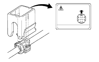
Check SST installation direction.
- SST
- 09870-00015
- HINT:
- Set SST so that the stopper side is on the piping clamp lock side.
PARKING BRAKE CABLE > REMOVAL |
| 1. PRECAUTION |
| 2. DISCHARGE REFRIGERANT FROM REFRIGERATION SYSTEM |
Turn the A/C switch on.
Operate the A/C with the setting temperature at 25 °C (77°F) and the blower level at LO for 10 minutes to circulate the refrigerant, and collect compressor oil remaining in each component into the cooler compressor as much as possible.
Stop the engine.
Recover the refrigerant from the A/C system using a refrigerant recovery unit.
| 3. DISCONNECT SUCTION HOSE SUB-ASSEMBLY |
|
Check SST installation direction.
Install SST on the piping clamp.
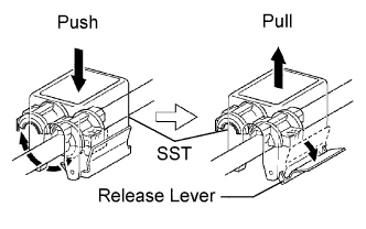 |
Push down on SST with your thumb while holding the pipe with both hands.
Pull SST until the stopper touches the pipe.
Raise SST stopper and remove the piping clamp with SST from the pipe.
Remove the piping clamp from SST.
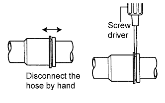 |
Disconnect the suction hose by hand or using a screwdriver.
Remove the 2 O-rings from the suction hose.
| 4. DISCONNECT COOLER REFRIGERANT LIQUID PIPE E (TO COOLER UNIT) |
| 5. DISCONNECT HEATER WATER HOSE B |
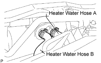 |
Slide the clip and disconnect the heater water hose B.
| 6. DISCONNECT HEATER WATER HOSE A |
Slide the clip and disconnect the heater water hose A.
| 7. REMOVE REAR NO. 2 FLOOR BOARD |
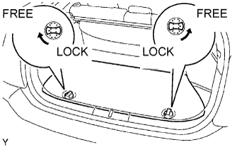 |
As shown in the illustration, turn the knob to release the lock.
Remove the rear floor board No. 2.
| 8. REMOVE REAR DECK FLOOR BOX |
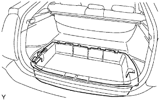 |
Remove the deck floor box rear shown in the illustration.
| 9. REMOVE REAR NO. 3 FLOOR BOARD |
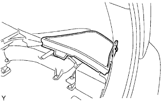 |
Remove the rear floor board shown in the illustration.
| 10. DISCONNECT CABLE FROM NEGATIVE BATTERY TERMINAL |
| 11. REMOVE INSTRUMENT PANEL SUB-ASSEMBLY |
Remove the instrument panel (Click here).
| 12. REMOVE NO. 2 STEERING WHEEL COVER LOWER |
| 13. REMOVE NO. 3 STEERING WHEEL COVER LOWER |
| 14. REMOVE STEERING PAD ASSEMBLY |
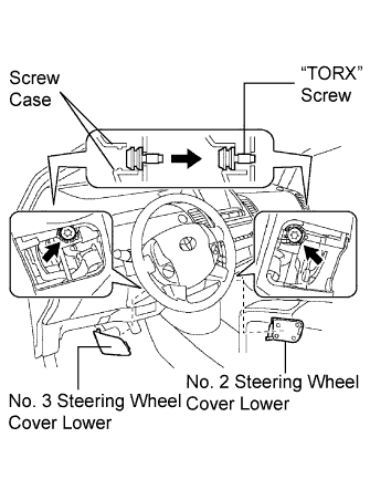 |
Straighten the front wheels.
Using a T30 "TORX" socket, loosen the 2 screws until the groove along each screw circumference catches on the screw case.
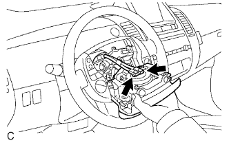 |
Pull out the steering pad from the steering wheel and support the steering pad with one hand as shown in the illustration.
Using a screwdriver, disconnect the 2 airbag connectors.
Disconnect the horn connector and remove the steering pad.
| 15. REMOVE STEERING WHEEL ASSEMBLY |
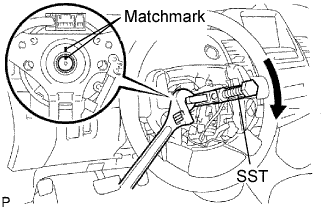 |
Remove the nut and put matchmarks on the steering wheel and steering main shaft.
Using SST, remove the steering wheel.
| 16. REMOVE TILT LEVER BRACKET |
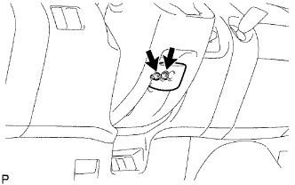 |
Remove the 2 screws and tilt lever bracket.
| 17. REMOVE STEERING COLUMN COVER |
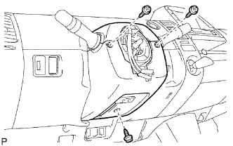 |
Detach the 4 claws and remove the 3 screws. Then remove the steering column lower cover and the steering column upper cover.
| 18. REMOVE TURN SIGNAL SWITCH ASSEMBLY WITH SPIRAL CABLE SUB-ASSEMBLY |
Remove the clamp and remove the turn signal switch from the steering column.
| 19. REMOVE FRONT DOOR SCUFF PLATE LH |
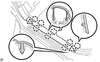 |
Using a screwdriver, detach the 8 claws and 2 clips, and remove the scuff plate.
| 20. REMOVE FRONT DOOR SCUFF PLATE RH |
| 21. REMOVE COWL SIDE TRIM BOARD LH |
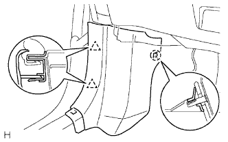 |
Using a screwdriver, detach the claw and 2 clips, and remove the trim board.
| 22. REMOVE COWL SIDE TRIM BOARD RH |
| 23. REMOVE CENTER INSTRUMENT CLUSTER FINISH PANEL ASSEMBLY |
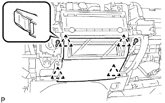 |
Remove the 2 screws.
Detach the 4 clips and remove the instrument cluster finish panel.
| 24. REMOVE RADIO RECEIVER ASSEMBLY |
| 25. REMOVE LOWER CENTER INSTRUMENT PANEL FINISH PANEL |
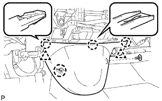 |
Using a clip remover, remove the clip from the instrument panel finish panel lower center.
Detach the 4 claws and 2 clips, and remove the instrument panel finish panel.
| 26. REMOVE GLOVE COMPARTMENT DOOR LOCK COVER |
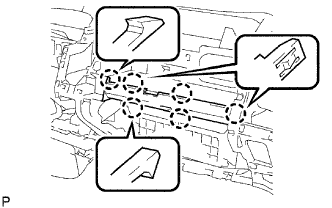 |
Detach the 6 claws and remove the glove compartment door lock cover.
| 27. REMOVE GLOVE COMPARTMENT DOOR LOCK ASSEMBLY |
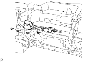 |
Remove the 4 screws and glove compartment door lock.
| 28. REMOVE LOWER INSTRUMENT PANEL FINISH PANEL |
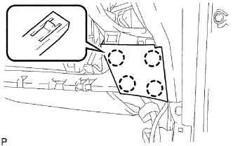 |
Detach the 4 claws and remove the instrument panel finish panel.
| 29. REMOVE NO. 1 INSTRUMENT PANEL UNDER COVER SUB-ASSEMBLY |
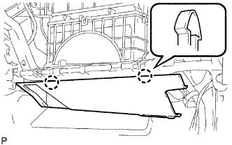 |
Detach the 2 claws and remove the instrument panel under cover.
| 30. REMOVE POWER STEERING ECU |
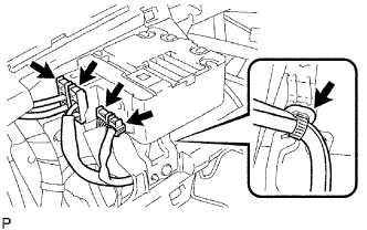 |
Separate the torque sensor wire harness clamp from the ECU.
Disconnect the 4 ECU connectors.
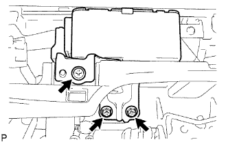 |
Remove the 3 screws and ECU.
| 31. REMOVE SHIFT LEVER ASSEMBLY |
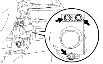 |
Remove the 3 bolts.
Disconnect the 2 connectors and remove the shift lever.
| 32. REMOVE REAR NO. 3 AIR DUCT |
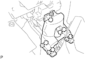 |
Fold back the floor carpet.
Detach the 10 claws and then remove the No. 3 air duct rear.
| 33. REMOVE NO. 3 HEATER TO REGISTER DUCT |
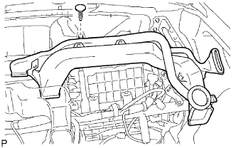 |
Remove the clip and No. 3 heater to register duct with the No. 2 side defroster nozzle duct.
| 34. REMOVE NO. 1 HEATER TO REGISTER DUCT |
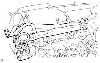 |
Remove the No. 1 duct with the No. 1 side defroster nozzle duct.
| 35. REMOVE NO. 2 HEATER TO REGISTER DUCT |
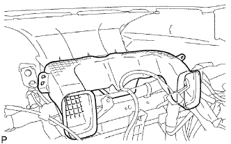 |
| 36. REMOVE DEFROSTER NOZZLE ASSEMBLY |
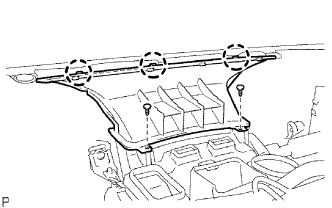 |
Remove the 2 clips.
Detach the 3 claws and then remove the defroster nozzle.
| 37. REMOVE ECM |
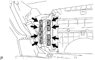 |
Disconnect the 4 ECM connectors.
Disconnect the 4 hybrid vehicle control ECU connectors.
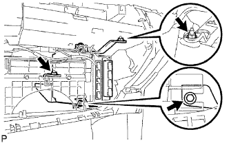 |
Remove the 2 nuts and bolt, and ECM with bracket.
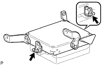 |
Remove the 2 nuts and ECM.
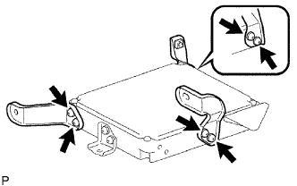 |
Remove the 6 screws and 3 No. 1 ECM brackets.
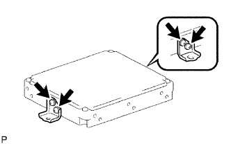 |
Remove the 4 screws and 2 No. 2 ECM brackets.
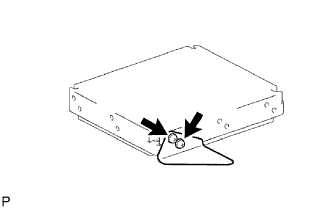 |
Remove the 2 screws and No. 3 ECM bracket.
| 38. REMOVE HYBRID VEHICLE CONTROL ECU |
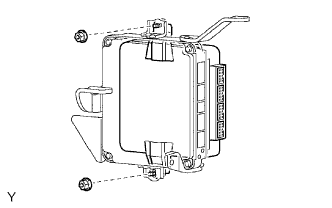 |
Remove the 2 nuts and hybrid vehicle control ECU.
| 39. REMOVE NETWORK GATEWAY ECU |
| 40. REMOVE NO. 1 INSTRUMENT PANEL BRACE SUB-ASSEMBLY |
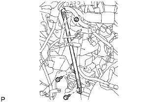 |
Detach the clamp and disconnect the harness.
Remove the 2 bolts, nut and instrument panel brace.
| 41. REMOVE AIR CONDITIONING AMPLIFIER ASSEMBLY |
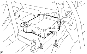 |
Disconnect the connector.
Remove the 2 screws and air conditioning amplifier.
| 42. REMOVE STEERING COLUMN ASSEMBLY |
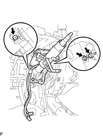 |
Disconnect the connectors and wire harness clamps from the steering column.
Remove the 3 bolts and steering column.
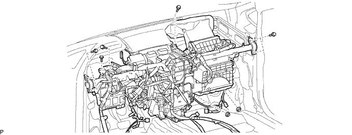
| 43. REMOVE INSTRUMENT PANEL REINFORCEMENT ASSEMBLY |
Disconnect each connector and remove each clamp. Disconnect the wire harness.
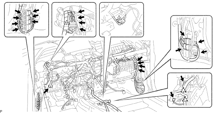
Remove the 7 bolts, 2 nuts and then remove the instrument panel reinforcement with the air conditioner unit.
| 44. REMOVE FRONT SEAT ASSEMBLY LH/RH |
Remove the front seat LH/RH (Click here).
| 45. REMOVE UPPER CONSOLE PANEL SUB-ASSEMBLY |
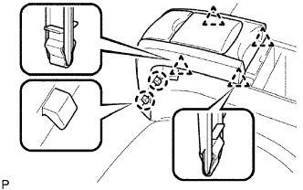 |
Pull the console panel sub-assembly upper upwards and disengage the 2 claws.
Detach the 4 clips and remove the console panel.
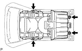 |
Remove the 4 screws and instrument panel cup holder.
| 46. REMOVE CONSOLE BOX POCKET |
| 47. REMOVE CONSOLE BOX CARPET |
| 48. REMOVE REAR CONSOLE BOX SUB-ASSEMBLY |
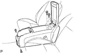 |
Remove the 2 screws, 2 bolts and console box.
| 49. REMOVE FRONT FLOOR FOOTREST |
Using a flat head screwdriver, pull the front floor footrest forward, detach the 2 clips, and remove the front floor footrest.
| 50. REMOVE CENTER AIRBAG SENSOR ASSEMBLY |
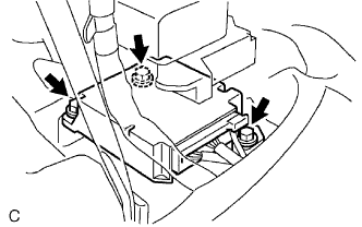 |
Remove the 3 bolts and airbag sensor.
Disconnect the airbag sensor connectors.
| 51. REMOVE YAW RATE SENSOR (w/ VSC) |
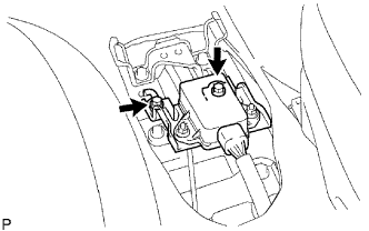 |
Disconnect the connector and remove the 2 bolts and sensor.
| 52. REMOVE NO. 1 CONSOLE BOX MOUNTING BRACKET |
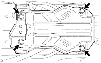 |
Remove the 2 bolts and No. 1 console box mounting bracket.
Remove the 2 bolts and No. 1 front floor side reinforcement.
| 53. REMOVE PARKING BRAKE CONTROL PEDAL ASSEMBLY |
Release the parking brake.
Remove the 2 No. 1 parking brake cable clamp nuts and parking brake front cable clamp.
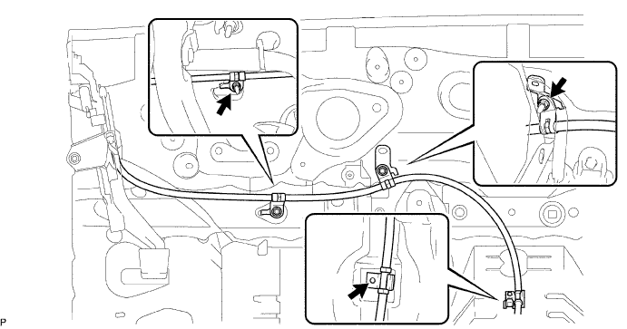
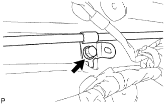 |
Remove the clamp bolt from the No. 1 parking brake cable.
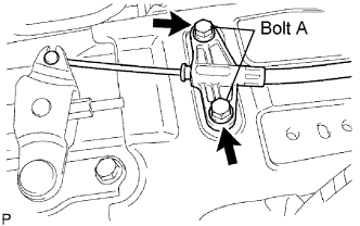 |
Disconnect the No. 1 parking brake cable from the parking brake intermediate lever.
Remove the 2 bolts labeled A shown in the illustration and separate the No. 1 parking brake cable from the floor.
Disconnect the connector from the parking brake switch connector and remove the harness clamp from the pedal bracket.
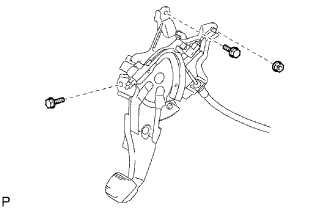 |
Remove the 2 bolts, nut and parking brake pedal.
| 54. REMOVE NO. 1 PARKING BRAKE CABLE ASSEMBLY |
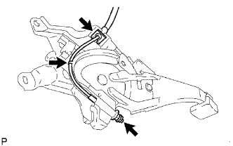 |
Unbend the parking brake pedal claw.
Remove the lock nut and adjusting nut of the No. 1 parking brake cable from the parking brake pedal.
Disengage the clip and remove the No. 1 parking brake cable from the parking brake pedal.
| 55. REMOVE REAR WHEEL |
| 56. REMOVE REAR BRAKE DRUM SUB-ASSEMBLY |
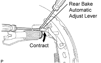 |
Put matchmarks on the rear brake drum and the axle hub.
Release the parking brake and remove the rear brake drum.
| 57. SEPARATE PARKING BRAKE SHOE STRUT SET LH |
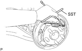 |
Using SST, disconnect the spring and parking brake shoe strut set from the brake shoes.
| 58. REMOVE FRONT BRAKE SHOE |
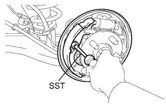 |
Using SST, remove the cup, shoe hold down spring and pin.
Remove the front brake shoe and tension spring.
| 59. REMOVE PARKING BRAKE SHOE STRUT SET LH |
Remove the parking brake shoe strut set from the rear brake shoe.
| 60. REMOVE REAR BRAKE AUTOMATIC ADJUST LEVER LH |
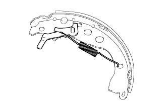 |
Remove the rear brake automatic adjust lever tension spring and the rear brake automatic adjust lever.
| 61. REMOVE REAR BRAKE SHOE |
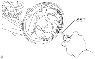 |
Remove the tension spring from the rear brake shoe.
Using SST, remove the cup, shoe hold down spring and pin.
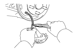 |
Using needle-nose pliers, disconnect the parking brake cable, and remove the rear brake shoe.
| 62. REMOVE REAR BRAKE PARKING BRAKE SHOE LEVER SUB-ASSEMBLY |
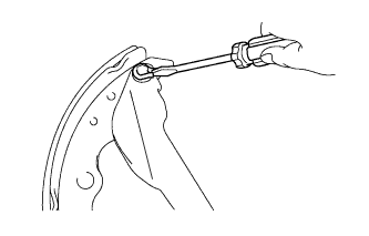 |
Using a screwdriver, remove the C-washer and parking brake shoe lever.
| 63. REMOVE HEATED OXYGEN SENSOR |
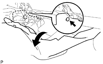 |
Using a clip remover, remove the clip.
Fold back the floor carpet front.
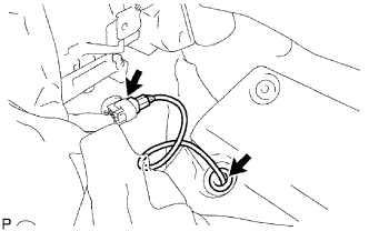 |
Disconnect the sensor connector.
Remove the grommet of the sensor from the vehicle.
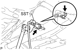 |
Remove the wire harness clamp bracket from the sensor.
Using SST, remove the sensor.
| 64. REMOVE FRONT FLOOR PANEL BRACE |
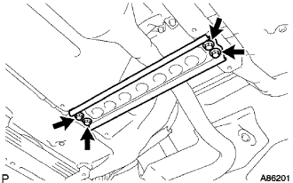 |
Remove the 2 bolts and floor panel brace.
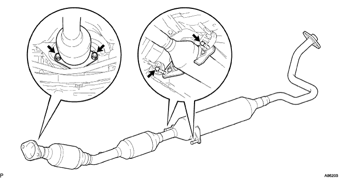
| 65. REMOVE FRONT EXHAUST PIPE ASSEMBLY |
Remove the 2 bolts and 2 compression springs.
Remove the front exhaust pipe from the 2 exhaust pipe supports.
Remove the gasket from the exhaust manifold.
| 66. REMOVE PARKING BRAKE CABLE HEAT INSULATOR |
Remove the 2 nuts and separate the parking brake cable heat insulator.
| 67. REMOVE NO. 3 PARKING BRAKE CABLE ASSEMBLY |
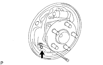 |
Remove the bolt and No. 3 parking brake cable from the backing plate.
Remove the bolts, button and No. 3 parking brake cable.
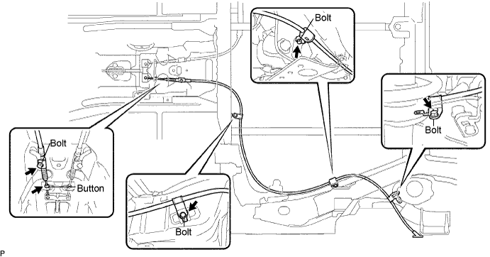
Disconnect the No. 3 parking brake cable from the parking brake equalizer.