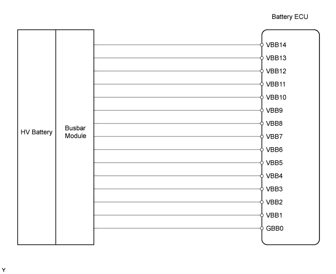
DTC P0AFA Hybrid Battery System Voltage Low |
| DTC No. | DTC Detection Condition | Trouble Area |
| P0AFA | Either of the following conditions occurs (1 trip detection logic)
|
|
| Related DTCs | P0AFA: Battery voltage sensor/Range check |
| Required sensors/components | The wire harness from each battery block to the battery ECU |
| Frequency of operation | Continuous |
| Duration | TOYOTA's intellectual property |
| MIL operation | Immediate |
| Sequence of operation | None |
| The monitor will run whenever the following DTCs are not present | TOYOTA's intellectual property |
| Other conditions belong to TOYOTA's intellectual property | - |
| Either of the following conditions is satisfied: | (a) or (b) |
| (a) Voltage at single battery block | Below 2 V |
| (b) Voltage of all battery blocks | -24 to 2 V |
| Battery ECU | No open malfunction |
| 1.READ DTC OUTPUT (DTC P0A1F IS OUTPUT) |
Connect the Techstream to the DLC3.
Turn the power switch ON (IG) and the tester ON.
Enter the following menus: Powertrain / HV Battery / DTC.
Read DTCs.
|
| ||||
| NO | |
 |
| 2.READ VALUE OF TECHSTREAM (BATTERY BLOCK VOL-V01 TO V14) |
Connect the Techstream to the DLC3.
Turn the power switch ON (IG) and the tester ON.
Enter the following menus: Powertrain / HV Battery / Data List.
Read "V1 to V14 Batt Block" on the tester.
|
| ||||
| NG | |
|
| 3.CHECK JUNCTION BLOCK ASSEMBLY (BUSBAR MODULE) |
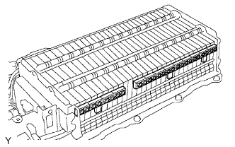 |
Remove the battery assembly (Click here).
Remove the battery cover (Click here).
Check that the nuts of the junction block are tightened to the specified torque.
|
| ||||
| OK | |
|
| 4.CHECK NO. 2 FRAME WIRE (BUSBAR MODULE) |
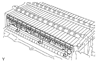 |
Check that the nuts of the No. 2 frame wire are tightened to the specified torque.
|
| ||||
| OK | |
|
| 5.CHECK CONNECTION OF NO. 2 FRAME WIRE CONNECTOR |
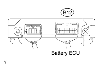 |
Check the connection condition of the B12 battery ECU connector.
|
| ||||
| OK | |
|
| 6.INSPECT NO. 2 FRAME WIRE (BUSBAR MODULE) |
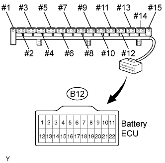 |
Remove the No. 2 frame wire (Click here).
Measure the resistance of each connector and the metal portions of the No. 2 frame wire.
| Tester Connection | Specified Condition |
| B12-22 (GBB0) - #1 | Below 1 Ω |
| B12-11 (VBB1) - #2 | Below 1 Ω |
| B12-21 (VBB2) - #3 | Below 1 Ω |
| B12-10 (VBB3) - #4 | Below 1 Ω |
| B12-20 (VBB4) - #5 | Below 1 Ω |
| B12-9 (VBB5) - #6 | Below 1 Ω |
| B12-19 (VBB6) - #7 | Below 1 Ω |
| B12-8 (VBB7) - #8 | Below 1 Ω |
| B12-18 (VBB8) - #9 | Below 1 Ω |
| B12-7 (VBB9) - #10 | Below 1 Ω |
| B12-17 (VBB10) - #11 | Below 1 Ω |
| B12-6 (VBB11) - #12 | Below 1 Ω |
| B12-16 (VBB12) - #13 | Below 1 Ω |
| B12-5 (VBB13) - #14 | Below 1 Ω |
| B12-15 (VBB14) - #15 | Below 1 Ω |
Reinstall the No. 2 frame wire.
|
| ||||
| OK | ||
 | ||
| ||

