 |
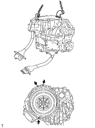
Install the 2 engine hangers in the positions shown in the illustration.
- HINT:
- Engine hanger: 12281-67070, S1228-11781
- Bolt: 91642-81045, 91642-81265
- Nut: 90178-10001, 90179-12147
HYBRID VEHICLE TRANSAXLE UNIT > DISASSEMBLY |
| 1. REMOVE HYBRID VEHICLE TRANSAXLE ASSEMBLY |
Remove the hybrid vehicle transaxle (Click here).
| 2. REMOVE HYBRID VEHICLE GENERATOR ASSEMBLY |
|
Install the 2 engine hangers in the positions shown in the illustration.
Using an engine sling device and chain block, set the transaxle with the generator side facing upward.
Remove the drain plug.
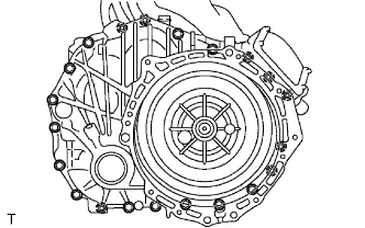 |
Remove the 21 bolts shown in the illustration.
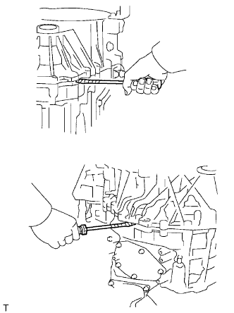 |
Disconnect the motor and generator by inserting a flat-head screwdriver in the position shown and prying the two apart.
Using an engine sling device and chain block, raise the generator.
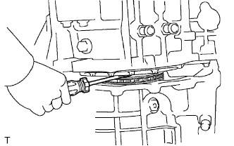 |
Apply protective tape to the head of a flat-head screwdriver and use it to hold down the chain with input shaft while removing the generator.
| 3. REMOVE COUNTER DRIVEN GEAR SUB-ASSEMBLY |
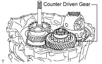 |
Remove the counter driven gear from the HV motor.
| 4. REMOVE DIFFERENTIAL CASE ASSEMBLY |
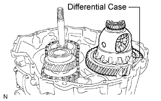 |
Remove the differential case from the HV motor.
| 5. REMOVE TRANSMISSION DRIVE SPROCKET SUB-ASSEMBLY |
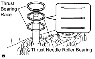 |
Remove the thrust bearing race, thrust needle roller bearing and No. 1 thrust bearing race.
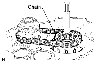 |
Remove the drive sprocket and chain.
| 6. REMOVE INPUT SHAFT ASSEMBLY |
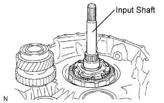 |
Remove the input shaft.
| 7. REMOVE PLANETARY RING GEAR |
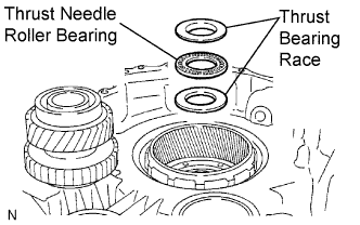 |
Remove the thrust bearing race, thrust needle roller bearing and No. 1 thrust bearing race.
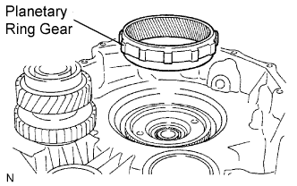 |
Remove the planetary ring rear.
| 8. REMOVE PLANETARY RING GEAR FLANGE |
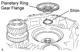 |
Remove the planetary ring gear flange and shim.
| 9. REMOVE SPROCKET DRIVEN GEAR AND COUNTER DRIVE GEAR |
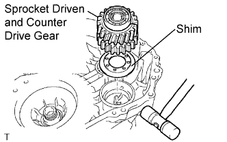 |
Using a plastic-faced hammer, tap the motor case and remove the counter drive gear and shim.
| 10. FIX TRANSMISSION OIL STRAINER |
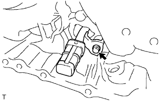 |
Remove the bolt and oil strainer.
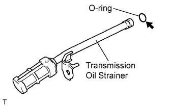 |
Remove the O-ring from the oil strainer.
| 11. REMOVE HV MOTOR ASSEMBLY |
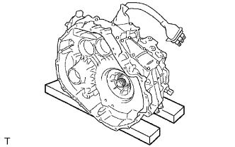 |
Place the motor on wooden blocks or equivalent.
| 12. REMOVE NO. 3 ENGINE MOUNTING BRACKET |
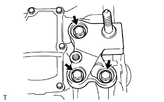 |
Remove the 3 bolts and mounting bracket.
| 13. REMOVE MOTOR REVOLUTION SENSOR WIRING HARNESS CONNECTOR |
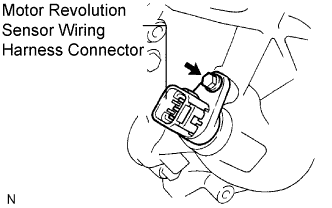 |
Remove the bolt and pull out the HV motor side motor revolution sensor wiring harness connector (gray).
Remove the connector and motor revolution sensor wiring harness connector (gray).
| 14. REMOVE MOTOR STATOR WIRING HARNESS CONNECTOR |
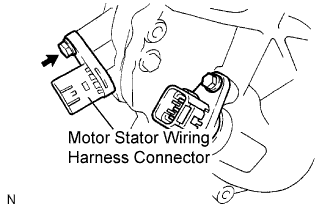 |
Remove the bolt and pull out the motor stator wiring harness connector (black).
Disconnect the connector and the motor stator wiring harness connector (black).
| 15. REMOVE SHIFT CONTROL ACTUATOR ASSEMBLY |
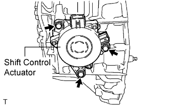 |
Remove the 3 bolts and shift control actuator.
| 16. REMOVE PARKING COVER |
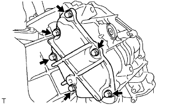 |
Remove the 6 bolts and parking cover.
| 17. REMOVE MANUAL DETENT SPRING SUB-ASSEMBLY |
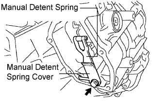 |
Remove the bolt, manual detent spring cover and manual detent spring.
| 18. REMOVE MOTOR WATER JACKET COVER |
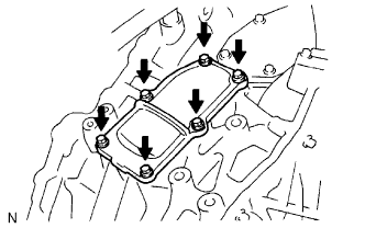 |
Remove the 6 bolts and motor water jacket cover.
| 19. REMOVE PARKING SHAFT COVER |
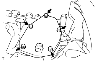 |
Remove the 5 bolts and parking shaft cover.
| 20. REMOVE TRANSMISSION OIL PUMP COVER SUB-ASSEMBLY |
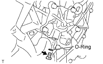 |
Remove the oil pump cover plug and O-ring.
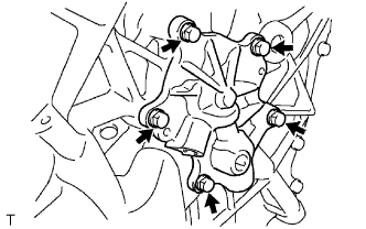 |
Remove the 5 bolts and oil pump cover.
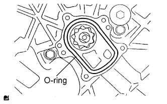 |
Remove the O-ring.
| 21. REMOVE OIL PUMP DRIVE SHAFT |
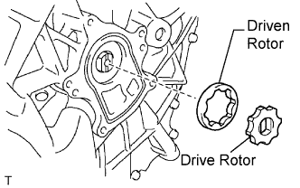 |
Remove the oil pump drive rotor and oil pump driven rotor.
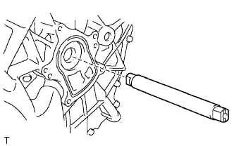 |
Remove the oil pump drive shaft.
| 22. REMOVE DIFFERENTIAL CASE LH TAPERED ROLLER BEARING RACE |
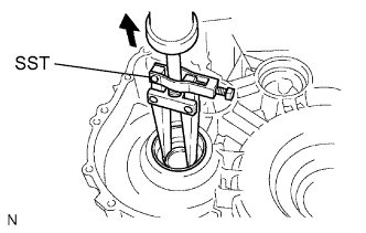 |
Using SST, tap out the differential case tapered roller bearing LH outer race and shim.
| 23. REMOVE HYBRID TRANSAXLE OIL SEAL LH |
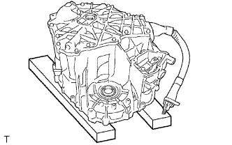 |
Place the motor on wooden blocks or equivalent.
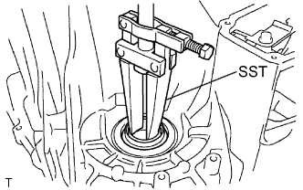 |
Using SST, tap out the oil seal.
| 24. REMOVE TRANSAXLE HOUSING AND CASE WITH HEAD STRAIGHT SCREW PLUG |
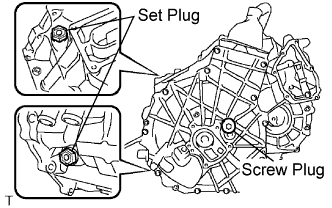 |
Remove the 2 set plugs and gasket.
Using a 10 mm hexagon wrench, remove the screw plugs.
| 25. FIX HYBRID VEHICLE GENERATOR ASSEMBLY |
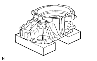 |
Place the generator on wooden blocks or equivalent.
| 26. REMOVE POWER CABLE COVER |
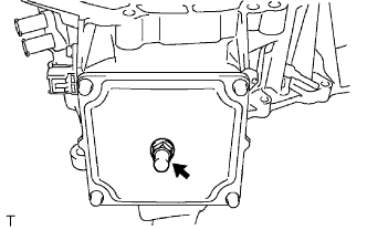 |
Remove the breather plug.
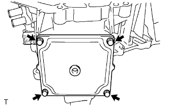 |
Remove the 4 bolts and power cable cover.
| 27. REMOVE GENERATOR CABLE |
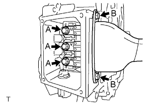 |
Remove the 5 bolts and generator cable.
| 28. REMOVE GENERATOR MOTOR REVOLUTION SENSOR WIRING HARNESS CONNECTOR |
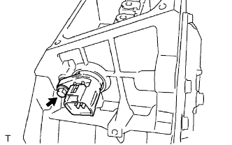 |
Remove the bolt and pull out the HV generator side generator revolution sensor wiring harness connector.
Disconnect the connector and the HV generator side generator revolution sensor wiring harness connector.
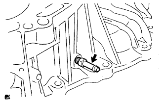
| 29. REMOVE TRANSAXLE HOUSING TUBE CONNECTOR |
 |
| 30. REMOVE HYBRID VEHICLE TRANSAXLE ASSEMBLY TYPE T OIL SEAL |
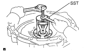 |
Using SST, remove the oil seal.
| 31. REMOVE HYBRID TRANSAXLE OIL SEAL RH |
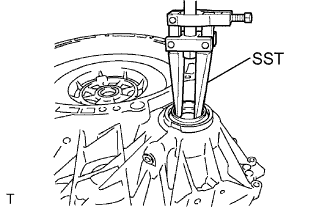 |
Using SST, tap out the oil seal.
| 32. REMOVE DIFFERENTIAL CASE RH TAPERED ROLLER BEARING RACE |
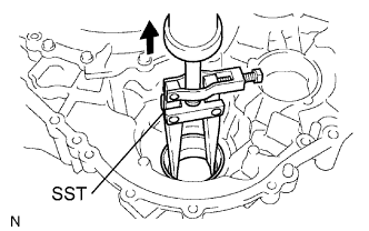 |
Using SST, tap out the differential case tapered roller bearing LH outer race.
| 33. REMOVE TRANSAXLE HOUSING AND CASE WITH HEAD STRAIGHT SCREW PLUG |
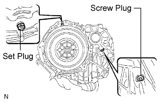 |
Remove the set plug and gasket.
Using a 6 mm socket wrench, remove the screw plug.