DTC P043E Evaporative Emission System Reference Orifice Clog Up |
DTC P043F Evaporative Emission System Reference Orifice High Flow |
DTC P2401 Evaporative Emission Leak Detection Pump Stuck OFF |
DTC P2402 Evaporative Emission Leak Detection Pump Stuck ON |
DTC P2419 Evaporative Emission Pressure Switching Valve Stuck ON |
| DTC No. | Monitoring Items | Malfunction Detection Conditions | Trouble Areas | Detection Timing | Detection Logic |
| P043E P043F P2401 P2402 P2419 | Reference orifice clogged | P043E, P043F, P2401, P2402 and P2419 are present when one of the following conditions is met during key-off EVAP monitor:
These values are typical |
| Power switch OFF | 2 trip |
| Components | Operations |
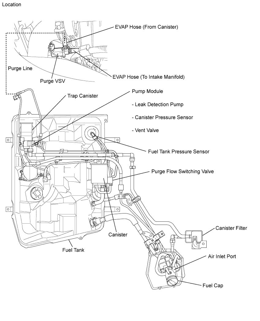
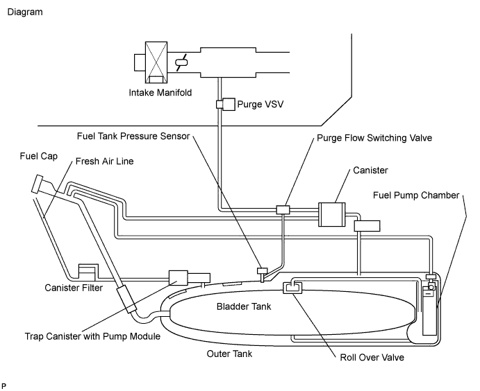
| Canister, Trap canister | Contains activated charcoal to absorb EVAP generated in fuel tank. |
| Cut-off valve | Located in fuel tank. Valve floats and closes when fuel tank is 100% full. |
| Purge Vacuum Switching Valve (VSV) | Opens or closes line between canister and intake manifold. ECM uses purge VSV to control EVAP purge flow. In order to discharge EVAP absorbed by canister to intake manifold, ECM opens purge VSV. EVAP discharge volume to intake manifold controlled by purge VSV duty cycle ratio (current-carrying time) (open: ON; closed: OFF). |
| Roll-over valve | Located in fuel tank. Valve closes by its own weight when vehicle overturns to prevent fuel from spilling out. |
| Soak timer | Built into ECM. To ensure accurate EVAP monitor, measures 5 hours (+-15 min) after power switch OFF. This allows fuel to cool down, stabilizing Fuel Tank Pressure (FTP). When approximately 5 hours elapsed, ECM activates. |
| Purge flow switching valve | The purge flow switching valve located on the canister is used to detect leakage from the bladder tank into the fuel tank. The valve opens during the bladder tank leak check. Then, the fuel tank's fuel vapor flows to the intake manifold without passing the canister. |
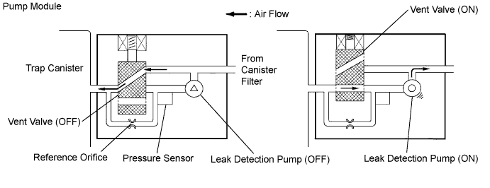
| Pump module | Consists of (a) to (d) below. Pump module cannot be disassembled. |
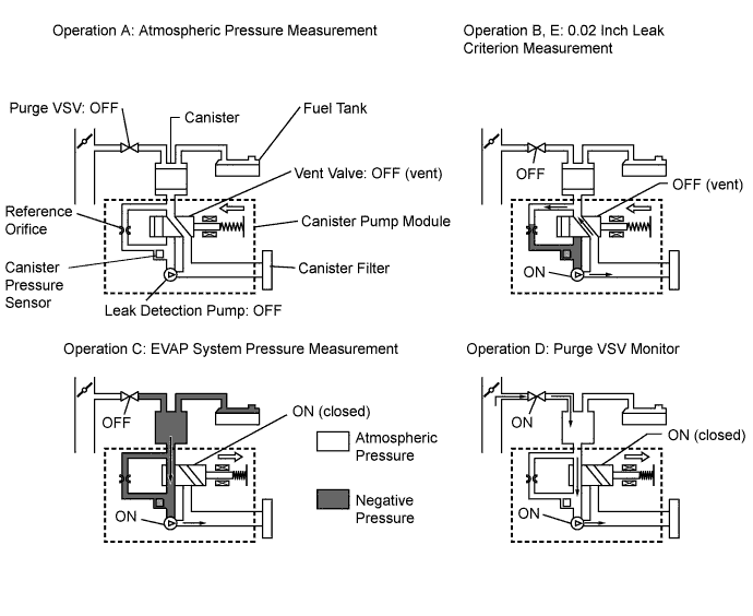
| (a) Vent valve | Vents and closes EVAP system. When ECM turns valve ON, EVAP system is closed. When ECM turns valve OFF, EVAP system is vented. Negative pressure (vacuum) created in EVAP system to check for EVAP leaks by closing purge VSV, turning vent valve ON (closed) and operating leak detection pump. |
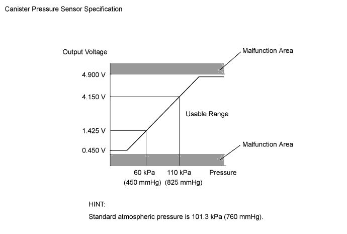
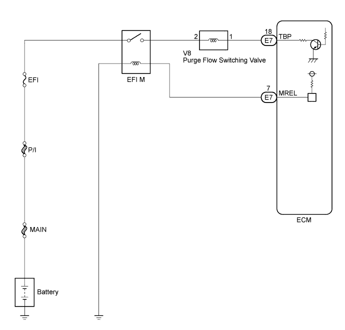
| (b) Canister pressure sensor | Indicates pressure as voltage. ECM supplies regulated 5 V to canister pressure sensor, and uses feedback from sensor to monitor EVAP system pressure. |
| (c) Leak detection pump | Creates negative pressure (vacuum) in EVAP system for leak check. |
| (d) Reference orifice | Has opening with 0.02 inch diameter. Vacuum produced through orifice by closing purge VSV, turning vent valve OFF and operating leak detection pump to monitor 0.02 inch leak criterion. 0.02 inch leak criterion indicates small leak of EVAP. |
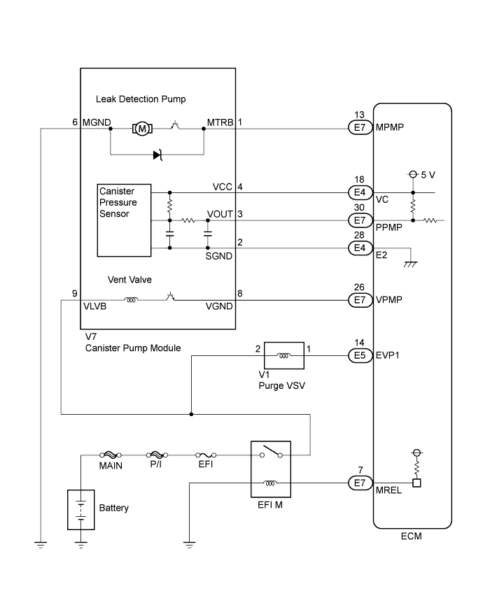
| Sequence | Operations | Descriptions | Duration |
| - | ECM activation | Activated by soak timer 5, 7 or 9.5 hours after power switch OFF. | - |
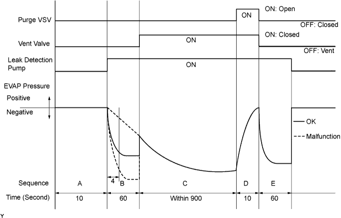
| A | Atmospheric pressure measurement | Vent valve turned OFF (vent) and EVAP system pressure measured by ECM in order to register atmospheric pressure. If pressure in EVAP system not between 70 kPa and 110 kPa (525 mmHg and 825 mmHg), ECM cancels EVAP system monitor. | 10 seconds |
| B | First 0.02 inch leak criterion measurement | In order to determine 0.02 inch leak criterion, leak detection pump creates negative pressure (vacuum) through reference orifice and then ECM checks if leak detection pump and vent valve operate normally. | 60 seconds |
| C | EVAP system pressure measurement | Vent valve turned ON (closed) to shut EVAP system. Negative pressure (vacuum) created in EVAP system, and EVAP system pressure then measured. Write down measured value as it will be used in leak check. If EVAP pressure does not stabilize within 900 seconds, ECM cancels EVAP system monitor. | 900 seconds* |
| D | Purge VSV monitor | Purge VSV opened and then EVAP system pressure measured by ECM. Large increase indicates normal. | 10 seconds |
| E | Second 0.02 inch leak criterion measurement | After second 0.02 inch leak criterion measurement, leak check performed by comparing first and second 0.02 inch leak criterion. If stabilized system pressure higher than second 0.02 inch leak criterion, ECM determines that EVAP system is leaking. | 60 seconds |
| - | Final check | Atmospheric pressure measured and then monitoring result recorded by ECM. | - |
| Related DTCs | P043E: 0.02 inch orifice clog (built-in pump module) P043F: 0.02 inch orifice high-flow (built-in pump module) P2401: Vacuum pump stuck OFF P2402: Vacuum pump stuck ON P2419: Vent valve stuck open (vent) |
| Required Sensors/Components | Purge VSV and canister pump module |
| Frequency of Operation | Once per driving cycle |
| Duration | Maximum 15 seconds |
| MIL Operation | 2 driving cycles |
| Sequence of Operation | None |
| The monitor will run whenever these DTCs are not present | None |
| Atmospheric pressure | 70 to 110 kPa (525 to 825 mmHg) |
| Battery voltage | 10.5 V or higher |
| Vehicle speed | Less than 2.5 mph (4 km/h) |
| Power switch | OFF |
| Time after key off | 5, 7 or 9.5 hours |
| EVAP pressure sensor malfunction (P0450, P0452, P0453) | Not detected |
| EVAP canister purge valve | Not operated by scan tool |
| EVAP canister vent valve | Not operated by scan tool |
| EVAP leak detection pump | Not operated by scan tool |
| Both of the following conditions 1 and 2 are met before key off | - |
| 1. Duration that vehicle has been driven | 5 minutes or more |
| 2. EVAP purge operation | Performed |
| ECT | 4.4 to 35°C (40 to 95°F) |
| IAT | 4.4 to 35°C (40 to 95°F) |
| Next sequence is run if the following condition is met | - |
| Atmospheric pressure change | Within 0.3 kPa (2.25 mmHg) in 1 second |
| Next sequence is run if the following conditions are met | - |
| EVAP pressure just after reference pressure measurement start | -1 kPa (-7.5 mmHg) or lower |
| Reference pressure | -4.85 to -1057 kPa (-36.38 to -7.93 mmHg) |
| Reference pressure | Saturated within 60 seconds |
| Next sequence is run if the following condition is met | - |
| EVAP pressure change after vent valve is ON | 0.3 kPa (2.25 mmHg) or more |
| Next sequence is run if the following condition is met | - |
| EVAP pressure | Saturated within 900 seconds |
| Next sequence is run if the following condition is met | - |
| EVAP pressure change after purge valve is open | 0.3 kPa (2.25 mmHg) or more |
| Next sequence is run if the following conditions are met | - |
| EVAP pressure just after reference pressure measurement start | -1 kPa (-7.5 mmHg) or lower |
| Reference pressure | -4.85 to -1.0572 kPa (-36.38 to -7.93 mmHg) |
| Reference pressure | Saturated within 60 seconds |
| Difference between first reference pressure and second reference pressure | Less than 0.7 kPa (5.25 mmHg) |
| Next sequence is run if the following condition is met | - |
| EVAP pressure when vacuum introduction is complete | Lower than second reference pressure |
| EVAP monitor is complete if the following condition is met | - |
| Atmospheric pressure difference between sequences 1 and 8 | Within 0.3 kPa (2.25 mmHg) |
| One of following conditions is met | - |
| EVAP pressure when just after reference pressure measurement start | More than -1 kPa (-7.5 mmHg) |
| Reference pressure | Less than -4.85 kPa (-36.38 mmHg) |
| Reference pressure | -1.0572 kPa (-7.93 mmHg) or higher |
| Reference pressure | Not saturated |
| Difference between first reference pressure and second reference pressure | 0.7 kPa (5.25 mmHg) or more |
| 1.CONFIRM DTC |
Turn the power switch OFF and wait for 10 seconds.
Turn the power switch ON (IG).
Turn the power switch OFF and wait for 10 seconds.
Connect Techstream to the DLC3.
Turn the power switch ON (IG).
Enter the following menus: Powertrain / Engine and ECT / Trouble Code.
Check if DTC P0446 is output.
|
| ||||
| YES | |
 |
| 2.PERFORM EVAPORATIVE SYSTEM CHECK |
Note the freeze frame data and DTCs.
Clear the DTCs.
Enter the following menus: Powertrain / Engine and ECT / Utility / Evaporative System Check / Automatic operation.
After the system check is finished, check for pending DTCs.
|
| ||||
| OK | |
|
| 3.CHECK OPERATION FOR PURGE FLOW SWITCHING VALVE |
Enter the following menus: Powertrain / Engine and ECT / Active Test / Activate the VSV for Tank Bypass.
Touch the purge flow switching valve (TANK BYPASS VSV) to feel the operating vibration.
|
| ||||
| OK | |
|
| 4.CHECK PURGE FLOW SWITCHING VALVE |
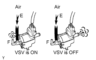 |
Turn the power switch OFF.
Remove the purge flow switching valve.
Reconnect the purge flow switching valve connector.
Enter the following menus: Powertrain / Engine and ECT / Active Test / Activate the VSV for Tank Bypass.
Check the airflow for the purge flow switching valve.
|
| ||||
|
| ||||
| 5.PERFORM EVAPORATIVE SYSTEM CHECK |
Enter the following menus: Powertrain / Engine and ECT / Utility / Evaporative System Check / Automatic Operation.
After the system check is finished, check for pending DTCs.
|
| ||||
| OK | |
|
| 6.CHECK DTC |
Check the DTCs that were present in the EVAP system check.
|
| ||||
| OK | |
|
| 7.CHECK VENT VALVE CLOSE STUCK |
Allow the engine to idle.
Enter the following menus: Powertrain / Engine and ECT / Active Test / Activate the VSV for Evap Control.
Turn the EVAP VSV ON (purge VSV open) and check the VAPOR PRESS (EVAP pressure) for 10 seconds.
|
| ||||
| OK | |
|
| 8.CHECK LEAK DETECTION PUMP OPERATION |
Turn the power switch OFF.
Turn the power switch ON (IG).
Enter the following menus: Powertrain / Engine and ECT / Active Test / Activate the Vacuum Pump.
Touch the pump module to feel the operating vibration.
|
| ||||
| OK | |
|
| 9.CHECK TRAP CANISTER |
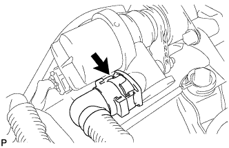 |
Disconnect the vent hose from the pump module.
Check that no moisture is in the pump module or the vent hose.
|
| ||||
|
| ||||
| 10.CHECK DTC |
Check the DTCs that were present in the EVAP system check.
|
| ||||
| OK | |
|
| 11.CHECK INSTALLATION CONDITION OF FUEL CAP |
Remove the fuel cap.
Reinstall the fuel cap.
Clear DTCs.
Enter the following menus: Powertrain / Engine and ECT / Utility / Evaporative System Check / Automatic Operation.
After the system check is finished, check for pending DTCs.
|
| ||||
| NG | |
|
| 12.LOCATE LEAK POINT |
Disconnect the vent hose (fresh air line) as shown in the illustration.
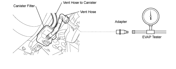
Connect the pressure gauge and air pump as shown in the illustration.
Pressurize the EVAP system until the pressure reaches 24 to 28 mmHg.
Locate the leak point.
|
| ||||
| NG | |
|
| 13.CHECK FUEL CAP |
|
| ||||
| OK | |
|
| 14.CHECK OPERATION FOR PURGE VSV |
Enter the following menus: Powertrain / Engine and ECT / Active Test / Activate the VSV for Evap Control.
Touch the purge VSV to feel the operating vibration.
|
| ||||
| OK | |
|
| 15.CHECK INTAKE MANIFOLD PRESSURE |
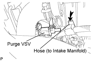 |
Disconnect the purge VSV hose that is connected to the throttle body.
Allow the engine to idle.
Check that the hose has suction using your finger.
|
| ||||
|
| ||||
| 16.CHECK DTC |
Check the DTCs that were present in the EVAP system check.
|
| ||||
| OK | |
|
| 17.CHECK OPERATION FOR VENT VALVE |
Enter the following menus: Powertrain / Engine and ECT / Active Test / Activate the VSV for Vent Valve.
Touch the pump module to feel the operating vibration.
|
| ||||
|
| ||||
| 18.CHECK HARNESS AND CONNECTOR (PURGE FLOW SWITCHING VALVE - ECM AND EFI M RELAY) |
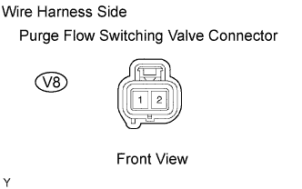 |
Check the harness and the connectors between the purge flow switching valve and the ECM.
Disconnect the V8 purge flow switching valve connector.
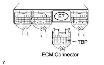 |
Disconnect the E7 ECM connector.
Measure the resistance according to the value(s) in the table below.
| Tester Connection | Specified Condition |
| V8-1 (Purge flow switching valve) - E7-18 (TBP) | Below 1 Ω |
| Tester Connection | Specified Condition |
| V8-1 (Purge flow switching valve) or E7-18 (TBP) - Body ground | 10 kΩ or higher |
Reconnect the purge flow switching valve connector.
Reconnect the ECM connector.
Check the harness and the connectors between the purge flow switching valve and the EFI M relay.
Disconnect the V8 purge flow switching valve connector.
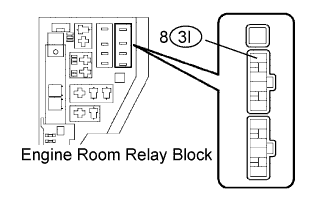 |
Remove the integration relay from the engine room relay block.
Measure the resistance according to the value(s) in the table below.
| Tester Connection | Specified Condition |
| V8-2 (purge flow switching valve) - 3I-8 (EFI M relay) | Below 1 Ω |
| Tester Connection | Specified Condition |
| V8-2 (purge flow switching valve) or 3I-8 (EFI M relay) - Body ground | 10 kΩ or higher |
Reconnect the purge flow switching valve connector.
Reinstall the integration relay.
|
| ||||
|
| ||||
| 19.REPLACE PURGE FLOW SWITCHING VALVE |
|
| ||||
| 20.CHECK FOR VENT HOSE CLOG |
Turn the power switch OFF.
|
Disconnect the vent hose (fresh air line) as shown in the illustration.
Allow the engine to idle.
Enter the following menus: Powertrain / Engine and ECT / Active Test / Activate the VSV for Evap Control.
Turn the purge VSV (EVAP VSV) ON and check the EVAP pressure (VAPOR PRESS) for 10 seconds.
|
| ||||
|
| ||||
| 21.CHECK HARNESS AND CONNECTOR (LEAK DETECTION PUMP - ECM) |
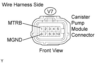 |
Disconnect the V7 canister pump module connector.
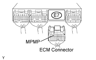 |
Disconnect the E7 ECM connector.
Measure the resistance according to the value(s) in the table below.
| Tester Connection | Specified Condition |
| V7-1 (MTRB) - E7-13 (MPMP) | Below 1 Ω |
| V7-6 (MGND) - Body ground | Below 1 Ω |
| Tester Connection | Specified Condition |
| V7-1 (MTRB) or E7-13 (MPMP) - Body ground | 10 kΩ or higher |
Reconnect the canister connector.
Reconnect the ECM connector.
|
| ||||
|
| ||||
| 22.REPLACE TRAP CANISTER WITH PUMP MODULE |
|
| ||||
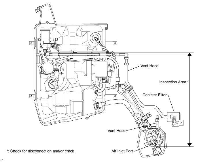
| 23.CHECK FOR VENT HOSE DAMAGE |
|
| ||||
| 24.REPAIR OR REPLACE LEAK POINT |
|
| ||||
| 25.REPLACE FUEL CAP |
|
| ||||
| 26.CHECK HARNESS AND CONNECTOR (PURGE VSV - ECM) |
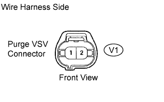 |
Disconnect the V1 purge VSV connector.
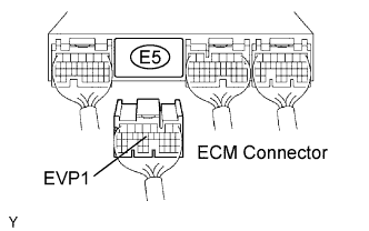 |
Disconnect the E5 ECM connector.
Check the harness and the connectors between the ECM and the purge VSV connectors.
Measure the resistance according to the value(s) in the table below.
| Tester Connection | Specified Condition |
| V1-1 - E5-14 (EVP1) | Below 1 Ω |
| Tester Connection | Specified Condition |
| V1-1 or E5-14 (EVP1) - Body ground | 10 kΩ or higher |
|
Remove the integration relay from the engine room relay block.
Check the harness and connectors between the purge VSV connector and the EFI M relay.
Measure the resistance according to the value(s) in the table below.
| Tester Connection | Specified Condition |
| V1-2 - 3I-8 (EFI M relay) | Below 1 Ω |
| Tester Connection | Specified Condition |
| V1-2 or 3I-8 (EFI M relay) - Body ground | 10 kΩ or higher |
Reconnect the purge VSV connector.
Reconnect the ECM connector.
Reinstall the integration relay.
|
| ||||
|
| ||||
| 27.REPLACE HOSE (PURGE VSV - THROTTLE BODY) |
|
| ||||
| 28.REPLACE PURGE VSV |
|
| ||||
| 29.CHECK HARNESS AND CONNECTOR (VENT VALVE - ECM) |
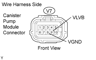 |
Disconnect the V7 canister pump module connector.
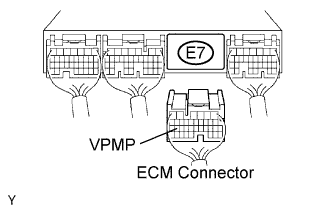 |
Disconnect the E7 ECM connector.
Check the harness and the connectors between the ECM and the canister connectors.
Measure the resistance according to the value(s) in the table below.
| Tester Connection | Specified Condition |
| V7-8 (VGND) - E7-26 (VPMP) | Below 1 Ω |
| Tester Connection | Specified Condition |
| V7-8 (VGND) or E7-26 (VPMP) - Body ground | 10 kΩ or higher |
|
Remove the integration relay from the engine room relay block.
Check the harness and connectors between the canister connector and the EFI M relay.
Measure the resistance according to the value(s) in the table below.
| Tester Connection | Specified Condition |
| V7-9 (VLVB) - 3I-8 (EFI M relay) | Below 1 Ω |
| Tester Connection | Specified Condition |
| V7-9 (VLVB) or 3I-8 (EFI M relay) - Body ground | 10 kΩ or higher |
Reconnect the canister connector.
Reconnect the ECM connector.
Reinstall the integration relay.
|
| ||||
|
| ||||
| 30.REPAIR OR REPLACE HARNESS OR CONNECTOR |
|
| ||||
| 31.REPLACE ECM |
|
| ||||
| 32.CHECK AND REPLACE VENT HOSE OR CANISTER FILTER |
|
| ||||
| 33.REPLACE HOSE (PURGE FLOW SWITCHING VALVE AND FUEL TANK) |
| NEXT | |
|
| 34.PERFORM EVAPORATIVE SYSTEM CHECK |
Turn the power switch ON (IG).
Enter the following menus: Powertrain / Engine and ECT / Utility / Evaporative System Check / Automatic Mode.
After the system check is finished, check for pending DTCs.
|
| ||||
| OK | |
|
| 35.PERFORM EVAP MONITOR DRIVE PATTERN |
Check that the following conditions are met:
Enter the check mode. Enter the following menus: Powertrain / Engine and ECT / Utility / Check Mode.
Allow the engine to idle until the ECT is 75°C (167°F).
Drive the vehicle at 50 km/h (30 mph) or faster and maintain that speed for 60 seconds or more.
Stop the vehicle. Do not turn the power switch OFF.
Check that the EVAP monitor status is complete. Enter the following menus: Powertrain / Engine and ECT / Monitor / Evaporative System.
If the EVAP monitor is incomplete, drive the vehicle at 50 km/h (30 mph) or faster and maintain that speed for 120 seconds or more. After that, recheck the EVAP monitor status.
Check for pending DTCs.
|
| ||||
| OK | ||
 | ||
| ||

