| NG |  |
| REPAIR OR REPLACE EXHAUST GAS LEAKAGE POINT |
DTC P0606 ECM / PCM Processor |
| DTC | DTC Setting Condition | Trouble Area |
| P0606 |
|
|
| Related DTC | P0606: ECM range check |
| Required sensors/Components (main) | ECM |
| Required sensors/Components (sub) | APP sensor, TP sensor, brake switch, cruise control, A/F sensor HO2S |
| Frequency of Operation | Continuous |
| Duration | 60 seconds |
| MIL Operation | Immediate |
| Sequence of Operation | None |
| Monitor will run whenever this DTC is not present | None |
| Engine | Running |
| Estimated A/F sensor temperature | 450 to 800°C (842 to 1,472°F) |
| Estimated HO2S temperature | 450 to 800°C (842 to 1,472°F) |
| Difference of main APP and sub APP | 0.3 V or more |
| Difference of main TP and sub TP | 0.3 V or more |
| Difference of main brake switch signal and sub brake switch signal | Different |
| Cruise control | Fail |
| A/F sensor transistors | Fail |
| HO2S transistors | Fail |
| 1.INSPECT FOR EXHAUST GAS LEAK |
Allow the engine to idle.
Check for exhaust gas leaks around the heated oxygen sensor.
|
| ||||
| OK | |
 |
| 2.CHECK HEATED OXYGEN SENSOR |
 |
Connect Techstream to the DLC3.
Start the engine and turn the tester on.
Warm up the engine at an engine speed of 2500 rpm for approximately 90 seconds.
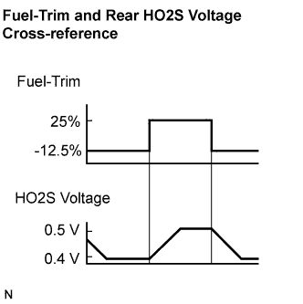
Select the following menu items: Powertrain / Engine and ECT / Active Test / Control the Injection Volume for A/F Sensor.
Perform the Control the Injection Volume for A/F Sensor operation with the engine in an idling condition (press the RIGHT or LEFT button to change the fuel injection volume).
Monitor the voltage outputs of the HO2 sensors (O2S B1S2) displayed on the tester.
| Tester Display (Sensor) | Injection Volumes | Voltages |
| O2S B1S2 | -12.5% | Less than 0.4 V |
| +25% | More than 0.5 V |
|
| ||||
| OK | |
|
| 3.CHECK WHETHER DTC OUTPUT RECURS (DTC P0606) |
 |
Connect Techstream to the DLC3.
Turn the power switch ON (IG) and turn the tester on.
Clear the DTC (Click here).
Turn the power switch OFF and turn the tester off.
Disconnect the battery negative terminal and wait for 1 minute.
Connect the battery negative terminal.
Start the engine.
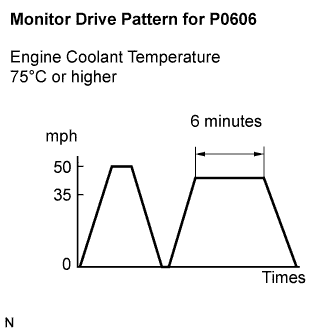
Perform the drive pattern.
Warm up the engine.
Accelerate the vehicle to 50 mph (80 km/h) and stop the vehicle.
Drive the vehicle at 35 to 50 mph (60 to 80 km/h) for 5 minutes or more.
Turn the tester on.
Select the following menu items: Powertrain / Engine and ECT / Trouble Code.
Read the DTCs.
| Display (DTC output) | Proceed to |
| P0606 | A |
| No output | B |
|
| ||||
| A | ||
 | ||
| ||