WIPER / WASHER WIPER AND WASHER SYSTEM GENERAL/CONTROL/DETAILS DETAILS
FUNCTION OF MAIN COMPONENTS
Wiper and Washer System
The wiper and washer system comprises the following parts and functions:
| Component | Function |
|---|---|
| Windshield Wiper Switch Assembly | Outputs the switch position signal to the windshield wiper motor assembly and the rear wiper motor assembly. |
| Front Wiper Motor and Link Assembly | Activates the front wiper arm and blade in accordance with position signal of the windshield wiper switch assembly. |
| Rear Wiper Motor Assembly | Activates the rear arm and blade in accordance with the position signal of the windshield wiper switch assembly. |
| Windshield Washer Jar Assembly | Activates the windshield washer motor and pump assembly, rear washer motor and pump assembly, headlight cleaner motor and pump assembly in accordance with the signal from the washer switch. |
Headlight Cleaner System
The headlight cleaner system comprises the following parts and functions:
| Component | Function |
|---|---|
| Headlight Cleaner Switch Assembly | The user operates this switch to operate the headlight cleaner headlight wiper switch assembly. |
| Headlight Cleaner Motor and Pump Assembly | Sends the washer fluid to the headlight cleaner in accordance with the signals from the headlight cleaner switch assembly. |
| Headlight Cleaner Control Relay | Receives the signals from the headlight cleaner switch assembly, washer switch and main body ECU and controls the headlight cleaner motor and pump assembly. |
| Main Body ECU | Sends the headlight low beam illumination signal to the headlight cleaner control relay. |
| Headlight Cleaner Actuator Sub-assembly | The pressure of the washer fluid sent by the headlight cleaner and motor assembly pushes out the headlight cleaner washer nozzles. |
| Headlight Cleaner Washer Nozzle | Sprays the washer fluid sent by the headlight cleaner and motor assembly onto the headlights. |
OPERATING CONDITION
Headlight Cleaner System
The headlight cleaner operates as follows:
| Headlight Low Beam | Headlight Cleaner Switch Assembly | Windshield Washer Switch Assembly | |
|---|---|---|---|
| ON | ON (First Time) | ON (Second Time or later) | |
| Turn on | Activated | Activated | Not Activated |
| Turn off | Activated | Not Activated | Not Activated |
SYSTEM CONTROL
Washer-Linked Wiper
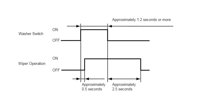
When the washer switch for either the front or rear wipers is held ON for approximately 0.5 to 1.2 seconds, the wipers start to operate almost simultaneously with the spraying of the washer fluid and stop when the switch is turned OFF. When held ON for longer than approximately 1.2 seconds, the operations above will continue for about 2.5 seconds after the switch is turned OFF.
Headlight Cleaner System
When the power switch is on, pressing the headlight cleaner switch assembly will cause the headlight cleaner and motor assembly to operate for a predetermined length of time.
When the power switch is on and the headlights are turned on to low beam, pressing the washer switch once will cause the headlight cleaner and motor assembly to operate.
CONSTRUCTION
Front Washer Nozzle
Spray type washer nozzles are located on the cowl top ventilator louver sub-assembly. These nozzles can spray windshield washer fluid over a wide area by spraying it in a fan shape. The washer fluid volume has been reduced so as not to hinder the driver's view when the washer system is operated.
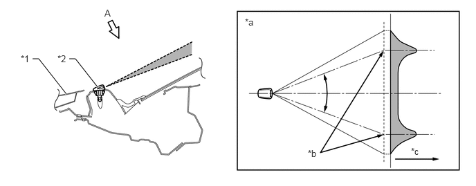
| *1 | Hood | *2 | Front Washer Nozzle |
| *a | Fluid Volume | *b | Main Flow Center |
| *c | View from A | - | - |
- HINT:
-
Spray type washer nozzles cannot be adjusted because of their structure. Do not attempt to adjust the nozzles as it could damage them. If adjustment is necessary, adjust the nozzles after replacing them with those selected from 3 part numbers with different spray angles. For details, refer to the Repair Manual.
Rear Washer Nozzle
Washer nozzle is located on the back door panel.
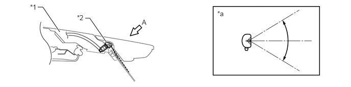
| *1 | Back Door Panel | *2 | Rear Washer Nozzle |
| *a | View from A | - | - |