Home › Engine / Hybrid System › 1NZ-FXE (ENGINE CONTROL) › CRANKSHAFT POSITION SENSOR
RM2170E _51 Engine / Hybrid System _057003 1NZ-FXE ENGINE CONTROL _0277916 CRANKSHAFT POSITION SENSOR A

1NZ-FXE ENGINE CONTROL  CRANKSHAFT POSITION SENSOR  INSTALLATION  


PROCEDURE

Hide 15100Q 1.INSTALL CRANK POSITION SENSOR
a.
A413180C02
1.531,1.948 1.531,1.542 false 1.521,4.052 1.521,3.646 false 2.146,1.938 1.917,1.938 1.917,1.938 1.781,1.344 true 2.438,4.042 2.208,4.042 2.208,4.042 2.073,3.448 true 2.854,1.354 3.094,1.354 false 2.865,3.458 3.104,3.458 false 0.125,0.073 0.5,0.365 0.375,0.292 12 false *A 0.156,2.375 0.521,2.698 0.365,0.323 12 false *B 1.479,1.948 1.792,2.104 0.313,0.156 10 false *a 1.479,4.042 1.792,4.198 0.313,0.156 10 false *a 2.188,1.865 2.344,2.063 0.156,0.198 10 false A 2.479,3.969 2.635,4.167 0.156,0.198 10 false A 3.125,1.281 3.344,1.531 0.219,0.25 10 false *b 3.146,3.385 3.365,3.635 0.219,0.25 10 false *b
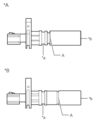
*A for Type A
*B for Type B
*a O-ring Groove
*b Crank Position Sensor Tip


Clean the O-ring groove of the crank position sensor.

NOTICE:

Make sure the O-ring groove is free of foreign matter.


b.

Apply protective tape around the part (A) shown in the illustration.


c.

Install a new O-ring to the crank position sensor.

NOTICE:

Set the O-ring on the tip of the crank position sensor and roll it into the O-ring groove with bare hands to install it.


d.
A407852C01
0.906,1.344 1.031,1.49 1.031,1.49 1.25,1.49 false 2.219,3.156 2.219,2.865 false 2.521,0.49 2.688,0.26 2.688,0.26 2.896,0.26 false 2.521,1.354 2.688,1.479 2.688,1.479 2.927,1.479 false 2.823,2.875 3.104,2.875 false 1.927,2.26 2.208,2.26 false 2.208,1.49 2.208,1.198 false 0.906,2.99 1.031,3.135 1.031,3.135 1.25,3.135 false 0.865,0.667 1.208,0.51 1.208,0.51 1.406,0.51 true 0.865,2.302 1.208,2.146 1.208,2.146 1.406,2.146 true 1.292,1.417 1.604,1.573 0.313,0.156 10 false *1 2.938,0.177 3.146,0.385 0.208,0.208 10 false *c 0.313,0.333 0.625,0.49 0.313,0.156 10 false *a 0.323,2 0.635,2.156 0.313,0.156 10 false *b 0.583,0.854 0.74,1.052 0.156,0.198 10 true A 1.031,0.854 1.188,1.052 0.156,0.198 10 true A 1.031,2.51 1.188,2.708 0.156,0.198 10 true B 0.604,2.51 0.76,2.708 0.156,0.198 10 true B 2.156,1.51 2.469,1.667 0.313,0.156 10 false *1 2.156,3.177 2.469,3.333 0.313,0.156 10 false *1 2.344,0.094 2.802,0.292 0.458,0.198 10 false A - A 2.354,1.875 2.813,2.073 0.458,0.198 10 false B - B 3.135,2.813 3.344,3.021 0.208,0.208 10 false *c 2.969,1.406 3.177,1.615 0.208,0.208 10 false *c 1.75,2.177 1.958,2.385 0.208,0.208 10 false *c 1.281,3.063 1.594,3.219 0.313,0.156 10 false *1 1.448,0.448 1.656,0.656 0.208,0.208 10 false *c 1.438,2.083 1.646,2.292 0.208,0.208 10 false *c
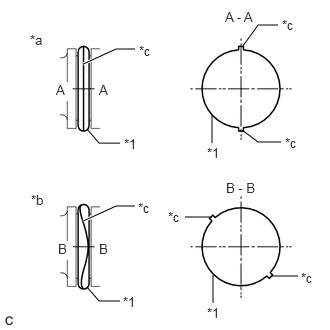
*1 O-ring
*a OK
*b NG
*c Seam


Check if the O-ring is twisted.

HINT:

Check the entire circumference of the seam of the O-ring for twisting.


e.

Remove the protective tape.

NOTICE:

Make sure to remove the protective tape and any tape adhesive residue.


f.
A413178C01
1.656,1.896 1.656,1.469 false 1.656,4.01 1.656,3.583 false 0.208,0.292 0.542,0.573 0.333,0.281 12 false *A 0.229,2.375 0.656,2.75 0.427,0.375 12 false *B 1.594,1.917 1.906,2.073 0.313,0.156 10 false *1 1.594,4.01 1.906,4.167 0.313,0.156 10 false *1
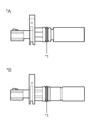
*A for Type A
*B for Type B
*1 O-ring


Apply a light coat of engine oil to the O-ring on the crank position sensor.


g.

Install the crank position sensor with the bolt.

Torque:
7.5 N*m (76 kgf*cm, 66 in.*lbf)

NOTICE:
·

If the crank position sensor has been struck or dropped, replace it.

·

Make sure that the O-ring is not cracked or does not move out of place during installation.


h.

Connect the crank position sensor connector.


Hide 2.INSPECT FOR OIL LEAK