RM2170E
_51
Engine / Hybrid System
_057003
1NZ-FXE ENGINE CONTROL
_0277922
INTEGRATION RELAY
G
1NZ-FXE ENGINE CONTROL INTEGRATION RELAY INSPECTION
PROCEDURE

 82641
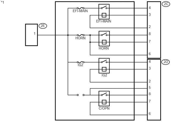
1.INSPECT NO. 1 INTEGRATION RELAY
1.33,1.244 1.461,1.447
0.132,0.202
10
1
1.612,0.928 1.824,1.088
0.212,0.160
10
2E
3.074,2.478 3.362,2.761
0.288,0.283
10
IG2
2.88,0.343 3.536,0.695
0.656,0.352
10
EFI-MAIN
3.807,0.748 4.463,1.064
0.656,0.315
10
EFI-MAIN
2.986,1.414 3.448,1.738
0.462,0.324
10
HORN
3.907,1.819 4.339,2.143
0.431,0.324
10
HORN
4.022,2.889 4.275,3.225
0.254,0.335
10
IG2
3.906,4.195 4.393,4.527
0.487,0.332
10
C/OPN
6.493,0.063 6.715,0.304
0.222,0.241
10
2C
6.48,2.357 6.679,2.591
0.199,0.235
10
2D
5.889,0.214 6.071,0.371
0.183,0.157
10
4
5.889,0.486 6.068,0.665
0.179,0.179
10
3
5.889,0.972 6.044,1.127
0.155,0.155
10
2
5.889,1.253 6.071,1.410
0.183,0.157
10
8
5.889,1.553 6.068,1.732
0.179,0.179
10
7
5.889,2.04 6.044,2.195
0.155,0.155
10
6
5.889,2.345 6.057,2.501
0.169,0.156
10
4
5.889,2.61 6.042,2.763
0.153,0.153
10
3
5.889,3.128 6.049,3.287
0.160,0.160
10
2
5.889,3.371 6.049,3.531
0.160,0.160
10
5
5.889,3.628 6.049,3.788
0.160,0.160
10
8
5.889,3.914 6.049,4.074
0.160,0.160
10
7
5.889,4.409 6.049,4.569
0.160,0.160
10
6
0.038,0.012 0.226,0.348
0.188,0.336
10
*1
| *1 | No. 1 Integration Relay | - | - |
a.
EFI-MAIN Relay:
i.
0.094,0.104 0.406,0.302
0.313,0.198
10
false
*1
0.448,0.719 0.76,0.917
0.313,0.198
10
false
2E
1.271,0.719 1.583,0.917
0.313,0.198
10
false
2D
2.406,0.708 2.719,0.906
0.313,0.198
10
false
2C
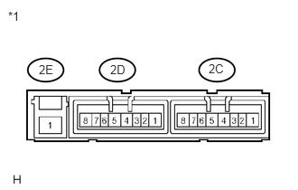
Measure the resistance according to the value(s) in the table below.
| *1 | No. 1 Integration Relay |
- Standard Resistance:
Tester Connection Condition Specified Condition No. 1 Integration relay (2E-1) - No. 1 Integration relay (2C-4) Auxiliary battery voltage is not applied between terminals 2C-3 and 2C-2 10 kΩ or higher No. 1 Integration relay (2E-1) - No. 1 Integration relay (2C-4) Auxiliary battery voltage is applied between terminals 2C-3 and 2C-2 Below 1 Ω
If the resistance is not as specified, replace the No. 1 integration relay.
b.
HORN Relay:
i.
0.094,0.104 0.406,0.302
0.313,0.198
10
false
*1
0.448,0.719 0.76,0.917
0.313,0.198
10
false
2E
1.271,0.719 1.583,0.917
0.313,0.198
10
false
2D
2.406,0.708 2.719,0.906
0.313,0.198
10
false
2C
Measure the resistance according to the value(s) in the table below.
| *1 | No. 1 Integration Relay |
- Standard Resistance:
Tester Connection Condition Specified Condition No. 1 Integration relay (2E-1) - No. 1 Integration relay (2C-8) Auxiliary battery voltage is not applied between terminals 2C-6 and 2C-7 10 kΩ or higher No. 1 Integration relay (2E-1) - No. 1 Integration relay (2C-8) Auxiliary battery voltage is applied between terminals 2C-6 and 2C-7 Below 1 Ω
If the resistance is not as specified, replace the No. 1 integration relay.
c.
IG2 Relay:
i.
0.094,0.104 0.406,0.302
0.313,0.198
10
false
*1
0.448,0.719 0.76,0.917
0.313,0.198
10
false
2E
1.271,0.719 1.583,0.917
0.313,0.198
10
false
2D
2.406,0.708 2.719,0.906
0.313,0.198
10
false
2C
Measure the resistance according to the value(s) in the table below.
| *1 | No. 1 Integration Relay |
- Standard Resistance:
Tester Connection Condition Specified Condition No. 1 Integration relay (2E-1) - No. 1 Integration relay (2D-4) Auxiliary battery voltage is not applied between terminals 2D-2 and 2D-3 10 kΩ or higher No. 1 Integration relay (2E-1) - No. 1 Integration relay (2D-4) Auxiliary battery voltage is applied between terminals 2D-2 and 2D-3 Below 1 Ω
If the resistance is not as specified, replace the No. 1 integration relay.
d.
C/OPN Relay:
i.
0.094,0.104 0.406,0.302
0.313,0.198
10
false
*1
0.448,0.719 0.76,0.917
0.313,0.198
10
false
2E
1.271,0.719 1.583,0.917
0.313,0.198
10
false
2D
2.406,0.708 2.719,0.906
0.313,0.198
10
false
2C
Measure the resistance according to the value(s) in the table below.
| *1 | No. 1 Integration Relay |
- Standard Resistance:
Tester Connection Condition Specified Condition No. 1 Integration relay (2D-5) - No. 1 Integration relay (2D-8) Auxiliary battery voltage is not applied between terminals 2D-6 and 2D-7 10 kΩ or higher No. 1 Integration relay (2D-5) - No. 1 Integration relay (2D-8) Auxiliary battery voltage is applied between terminals 2D-6 and 2D-7 Below 1 Ω
If the resistance is not as specified, replace the No. 1 integration relay.