HYBRID / BATTERY CONTROL HYBRID CONTROL SYSTEM P0AC0-817 Hybrid Battery Pack Current Sensor Circuit Range / Performance
DESCRIPTION
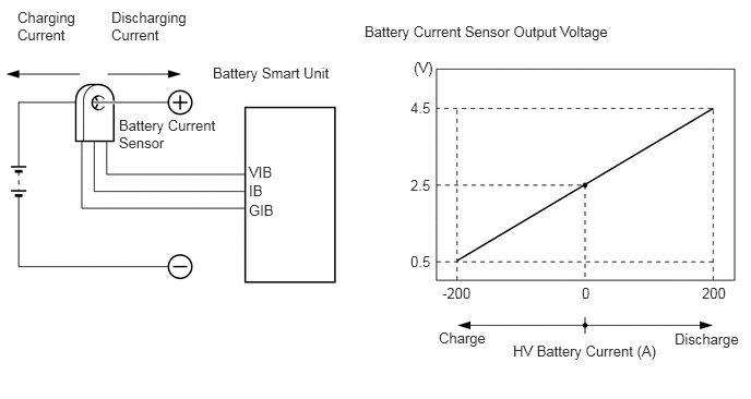
The battery current sensor, which is located in the hybrid battery junction block assembly on the positive side of the HV battery, detects the amperage that flows to and from the HV battery. The battery smart unit receives a voltage of between 0 and 5 V that is in proportion to the amperage flowing in the cable. This voltage goes into the IB terminal from the battery current sensor. A battery current sensor output voltage below 2.5 V indicates that the HV battery is being charged, and a voltage above 2.5 V indicates that the HV battery is being discharged. The power management control ECU determines the amount of either charge or discharge amperage that is being received by the HV battery based on the signals that are input to terminal IB of the battery smart unit from the battery current sensor. The power management control ECU also calculates the SOC (state of charge) of the HV battery based on the accumulated amperage.
| DTC No. | INF Code | DTC Detection Condition | Trouble Area |
|---|---|---|---|
| P0AC0 | 817 | HV battery current sensor performance problem | ·
Hybrid battery junction block assembly ·
Battery smart unit |
CAUTION / NOTICE / HINT
- HINT:
-
After the repair, clear the DTCs and perform the following procedure to check that DTCs are not output.
- 1.
Drive the vehicle for approximately 10 minutes according to the freeze frame data items "Vehicle Spd", "Accelerator Degree", "Power Resource IB", "M(MG2) Trq Exec Val" and "G(MG1) Trq Exec Val".
PROCEDURE
Connect the intelligent tester to the DLC3.
Turn the power switch on (IG).
Enter the following menus: Powertrain / Hybrid Control / DTC.
Check if DTCs are output.
- Result:
Result Proceed to P0AC0-817 only is output. A P0AFC-123 is output. B
Turn the power switch off.
A
B
NEXT
Connect the intelligent tester to the DLC3.
Turn the power switch on (IG).
Enter the following menus: Powertrain / Hybrid Control / DTC.
Read and record the DTCs and freeze frame data.
Clear DTCs and freeze frame data.
Turn the power switch off.
NEXT
NEXT
Connect the intelligent tester to the DLC3.
Turn the power switch on (IG).
Enter the following menus: Powertrain / Hybrid Control / DTC.
Check if DTCs are output.
- Result:
Result Proceed to P0AC0-817 is not output. A P0AC0-817 is output again. B
Turn the power switch off.
A
B