HYBRID / BATTERY CONTROL HYBRID CONTROL SYSTEM P0C3A-621 DC / DC Converter Temperature Sensor "A" Low P0C3B-622 DC / DC Converter Temperature Sensor "A" High P0C3F-623 DC / DC Converter Temperature Sensor "B" Low P0C40-624 DC / DC Converter Temperature Sensor "B" High
DESCRIPTION
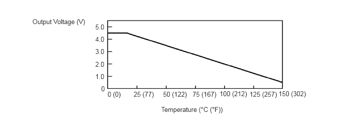
The MG ECU detects the temperature of the boost converter using the temperature sensor built into the boost converter. The boost converter using the temperature sensor outputs voltage which changes between 0.5 and 4.5 V in response to a change in temperature. The higher the boost converter temperature, the lower the output voltage. Conversely, the lower the boost converter temperature, the higher the output voltage. The MG ECU limit load based on signals sent from the boost converter temperature sensor to help prevent overheating. The MG ECU also detects malfunctions in the boost converter temperature sensor and its wiring.
| DTC No. | INF Code | DTC Detection Condition | Trouble Area |
|---|---|---|---|
| P0C3A | 621 | Open or short to GND in the boost converter temperature sensor (upper) signal circuit | Inverter with converter assembly |
| P0C3B | 622 | Short to +B in the boost converter temperature sensor (upper) signal circuit | |
| P0C3F | 623 | Open or short to GND in the boost converter temperature sensor (lower) signal circuit | |
| P0C40 | 624 | Short to +B in the boost converter temperature sensor (lower) signal circuit |
CAUTION / NOTICE / HINT
- HINT:
-
After the repair, clear the DTCs and perform the following procedure to check that DTCs are not output.
- 1.
Turn the power switch on (IG) and wait for 5 seconds or more.
PROCEDURE
NEXT