Home › Engine / Hybrid System › HYBRID / BATTERY CONTROL › HYBRID CONTROL SYSTEM › 2011.12–2014.12
RM2170E _51 Engine / Hybrid System _057004 HYBRID / BATTERY CONTROL _0277924 HYBRID CONTROL SYSTEM C

HYBRID / BATTERY CONTROL  HYBRID CONTROL SYSTEM  P3110-223  HV Main Relay  


DESCRIPTION

The power management control ECU monitors the IGCT relay and detects the following malfunction.

DTC No. INF Code DTC Detection Condition Trouble Area
P3110 223 There is a short to +B in the IGCT relay or the IGCT relay is stuck closed.
·

Wire harness or connector

·

IGCT relay

·

Power management control ECU


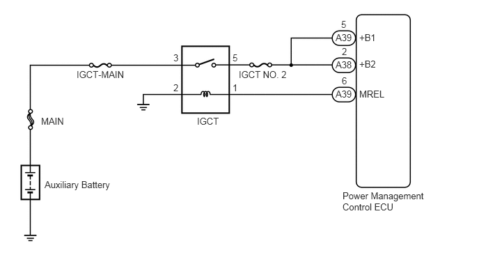
WIRING DIAGRAM

A270250E06
5.125,2.844 6.375,3.396 1.25,0.552 10 false Power Management Control ECU 5.375,0.479 5.688,0.646 0.313,0.167 10 false +B1 5.375,0.875 5.688,1.042 0.313,0.167 10 false +B2 5.375,1.323 5.792,1.49 0.417,0.167 10 false MREL 5.021,0.479 5.292,0.646 0.271,0.167 10 false A39 5.104,0.281 5.219,0.448 0.115,0.167 10 false 5 5.115,0.688 5.229,0.854 0.115,0.167 10 false 2 5.115,1.125 5.229,1.292 0.115,0.167 10 false 6 5.021,0.885 5.292,1.052 0.271,0.167 10 false A38 5.021,1.323 5.292,1.49 0.271,0.167 10 false A39 3.573,1.031 4.365,1.198 0.792,0.167 10 false IGCT NO. 2 2.948,1.729 3.531,1.896 0.583,0.167 10 false IGCT 3.479,0.781 3.594,0.948 0.115,0.167 10 false 5 3.479,1.229 3.594,1.396 0.115,0.167 10 false 1 2.594,1.229 2.708,1.396 0.115,0.167 10 false 2 2.594,0.781 2.708,0.948 0.115,0.167 10 false 3 0.667,2.677 1.75,2.844 1.083,0.167 10 false Auxiliary Battery 1.146,1.031 1.958,1.208 0.813,0.177 10 false IGCT-MAIN 0.615,1.729 1.073,1.906 0.458,0.177 10 false MAIN

CAUTION / NOTICE / HINT

HINT:
·

When the circuit is shorted to +B, the auxiliary battery voltage will be applied to terminal +B1 or +B2 of the power management control ECU, even though the power switch is off.

·

After the repair, clear the DTCs and perform the following procedure to check that DTCs are not output.

(a)

Turn the power switch on (IG) and wait for 15 seconds or more.

(b)

Turn the power switch off and wait for 30 seconds or more.


PROCEDURE

1.INSPECT RELAY (IGCT)
a.

Remove the IGCT relay from the No. 2 engine room relay block and No. 2 junction block assembly.
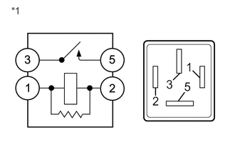

b.
A253297E01
0.165,0.068 0.398,0.266 0.232,0.198 10 *1

Measure the resistance according to the value(s) in the table below.
Standard Resistance:
Tester Connection Condition Specified Condition
3 - 5 Auxiliary battery voltage is not applied between terminals 1 and 2 10 kΩ or higher


Text in Illustration
*1 IGCT Relay


c.

Install the IGCT relay.


OK

2.CHECK HARNESS AND CONNECTOR (POWER MANAGEMENT CONTROL ECU - NO.2 ENGINE ROOM RELAY BLOCK AND NO. 2 JUNCTION BLOCK ASSEMBLY)

NG

REPLACE RELAY (IGCT)

2.CHECK HARNESS AND CONNECTOR (POWER MANAGEMENT CONTROL ECU - NO.2 ENGINE ROOM RELAY BLOCK AND NO. 2 JUNCTION BLOCK ASSEMBLY)
a.

Remove the IGCT relay from the No. 2 engine room relay block and No. 2 junction block assembly.


b.

Disconnect connector A38 and A39 from the power management control ECU.


c.

Measure the voltage according to the value(s) in the table below.

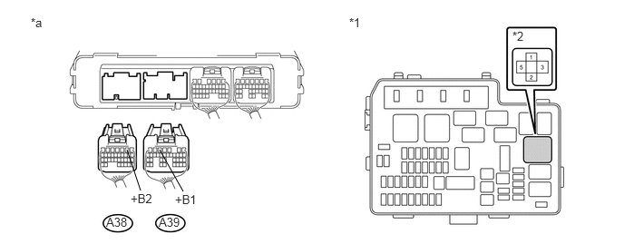
U183300E02
1.458,1.719 1.615,2.188 false 1.833,1.719 2.104,2.198 false 0.354,0.177 0.542,0.396 0.188,0.219 10 false *a 4.01,0.177 4.198,0.396 0.188,0.219 10 false *1 5.885,0.333 6.073,0.552 0.188,0.219 10 false *2 1.5,2.198 1.802,2.396 0.302,0.198 10 false +B2 2.01,2.208 2.313,2.406 0.302,0.198 10 false +B1 1.219,2.469 1.49,2.635 0.271,0.167 10 false A38 1.823,2.469 2.094,2.635 0.271,0.167 10 false A39

Text in Illustration
*1 No. 2 Engine Room Relay Block and No. 2 Junction Block Assembly *2 IGCT relay
*a Rear view of wire harness connector
(to Power Management Control ECU)
- -

Standard Voltage:
Tester Connection Switch Condition Specified Condition
A39-5 (+B1), A38-2 (+B2) or 5 (IGCT relay) - Body ground Power switch off Below 1 V


d.

Install the IGCT relay.


e.

Connect the power management control ECU connector.


OK

NG

REPAIR OR REPLACE HARNESS OR CONNECTOR