RM2170E
_51
Engine / Hybrid System
_057004
HYBRID / BATTERY CONTROL
_0277935
COMBINATION SWITCH
G
HYBRID / BATTERY CONTROL COMBINATION SWITCH INSPECTION
PROCEDURE

 84720J
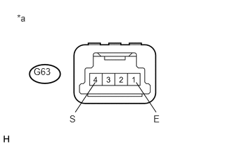
1.INSPECT EV DRIVE MODE SWITCH (PATTERN SELECT SWITCH ASSEMBLY)
a.
0.254,0.187 0.438,0.352
0.184,0.165
10
*a
0.5,0.993 0.795,1.156
0.295,0.163
10
G63
1.038,1.703 1.150,1.866
0.112,0.163
10
S
1.124,1.681 1.422,1.234
false
2.293,1.703 2.405,1.866
0.112,0.163
10
E
2.333,1.681 2.035,1.234
false
Measure the resistance according to the value(s) in the table below.
- Standard Resistance:
Tester Connection Condition Specified Condition G63-4 (S) - G63-1 (E) EV drive mode switch (pattern select switch assembly) being pushed and held Below 1 Ω G63-4 (S) - G63-1 (E) EV drive mode switch (pattern select switch assembly) not pushed 10 kΩ or higher
| *a | Component without harness connected
(EV Drive Mode Switch (Pattern Select Switch Assembly)) |
If the result is not as specified, replace the EV drive mode switch (pattern select switch assembly).
b.
1.125,1.677 1.594,1.229
false
2.302,1.677 1.844,1.208
false
0.25,0.188 0.438,0.354
0.188,0.167
10
false
*a
0.531,1.021 0.854,1.188
0.323,0.167
10
false
G63
0.969,1.729 1.292,1.896
0.323,0.167
10
false
ILL+
2.229,1.75 2.552,1.917
0.323,0.167
10
false
ILL-
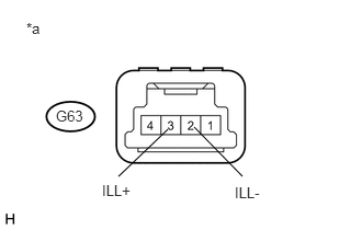
Apply auxiliary battery voltage between the terminals of the switch, and check the illumination condition of the EV drive mode switch (pattern select switch assembly).
- OK:
Measurement Condition Specified Condition Auxiliary battery positive (+) → G63-3 (ILL+) Auxiliary battery negative (-) →G63-2 (ILL-) Illuminates
| *a | Component without harness connected
(EV Drive Mode Switch (Pattern Select Switch Assembly)) |
If the result is not as specified, replace the EV drive mode switch (pattern select switch assembly).