RM2170E
_51
Engine / Hybrid System
_057004
HYBRID / BATTERY CONTROL
_0277939
INVERTER CURRENT SENSOR
A
HYBRID / BATTERY CONTROL INVERTER CURRENT SENSOR DISASSEMBLY
CAUTION / NOTICE / HINT
- HINT:
-
For the disassembly procedure of the inverter with converter assembly, refer to the disassembly procedure of the MG control computer with bracket sub-assembly (See page Engine / Hybrid System>HYBRID / BATTERY CONTROL>MOTOR GENERATOR CONTROL COMPUTER>DISASSEMBLY).
PROCEDURE

 1.REMOVE INVERTER CURRENT SENSOR SUB-ASSEMBLY
a.
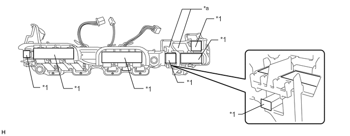
Apply protective tape to the inverter terminal with sensor sub-assembly as shown in the illustration.
- NOTICE:
-
Use non-residue type tape.
4,0.969 4.229,0.385
4.229,0.385 4.385,0.385
false
4.063,1.229 4.323,0.823
4.323,0.823 4.469,0.823
false
3.646,0.99 3.906,0.188
false
3.458,0.979 3.729,0.188
3.729,0.188 4.135,0.188
false
2.552,1.188 2.75,1.823
2.75,1.823 2.938,1.823
false
1.115,1.125 1.302,1.823
1.302,1.823 1.49,1.823
false
0.542,1.135 0.688,1.802
0.688,1.802 0.823,1.802
false
3.458,1.24 3.635,1.698
3.635,1.698 3.771,1.698
false
5.406,2.146 4.958,2.354
4.958,2.354 4.875,2.354
false
4.417,0.302 4.646,0.521
0.229,0.219
10
false
*1
4.51,0.729 4.74,0.948
0.229,0.219
10
false
*1
2.979,1.75 3.208,1.969
0.229,0.219
10
false
*1
1.521,1.74 1.75,1.958
0.229,0.219
10
false
*1
0.865,1.719 1.094,1.938
0.229,0.219
10
false
*1
3.823,1.615 4.052,1.833
0.229,0.219
10
false
*1
4.698,2.271 4.927,2.49
0.229,0.219
10
false
*1
4.167,0.094 4.396,0.292
0.229,0.198
8
false
*a
| *1 | Protective Tape | - | - |
| *a | Terminal Tray | - | - |
b.
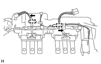
Disengage the 2 wire harnesses of the inverter current sensor sub-assembly from each clamp as shown in the illustration.
c.
2.753,0.966 2.953,0.39
false
2.821,0.393 3.118,0.393
false
2.624,0.963 2.823,0.387
false
3.147,0.296 3.377,0.516
0.230,0.221
10
*a
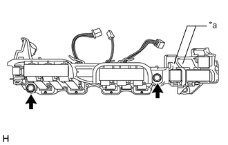
Remove the 2 bolts and inverter current sensor sub-assembly.
- NOTICE:
-
Do not touch the bus-bars.
| *a | Terminal Tray |