RM2170E
_51
Engine / Hybrid System
_057006
1NZ-FXE FUEL
_0277957
FUEL SENDER GAUGE ASSEMBLY
G
1NZ-FXE FUEL FUEL SENDER GAUGE ASSEMBLY INSPECTION
PROCEDURE

 83320
1.INSPECT FUEL SENDER GAUGE ASSEMBLY
a.
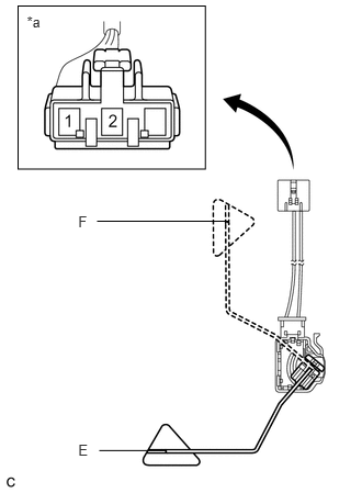
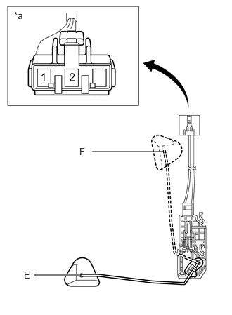
Check that the float moves smoothly between F and E.
b.
0.171,0.057 1.949,1.604
1.779,1.547
0.255,0.123 0.425,0.301
0.170,0.178
10
*a
0.743,2.016 0.880,2.170
0.138,0.154
10
F
0.743,4.192 0.880,4.346
0.138,0.154
10
E
2.166,2.099 0.921,2.099
false
1.58,4.275 0.943,4.275
false
Measure the resistance between terminals 1 and 2 of the connector according to the value(s) in the table below. (Type A)
| *a | Component without harness connected
(Fuel Sender Gauge Assembly) |
- Standard Resistance:
Tester Connection Float Level Specified Condition 1 - 2 F 12.0 to 18.0 Ω Between F and E 12.0 to 415.0 Ω (Gradually changes) E 405.0 to 415.0 Ω
If the value is not as specified, replace the fuel sender gauge assembly.
c.
0.115,0.094 2.052,1.563
1.938,1.469
1.188,4.083 0.51,4.083
true
2.417,2.25 1.365,2.25
false
0.208,0.146 0.729,0.542
0.521,0.396
10
false
*a
0.354,4 0.677,4.229
0.323,0.229
10
false
E
1.177,2.167 1.396,2.396
0.219,0.229
10
false
F
Measure the resistance between terminals 1 and 2 of the connector according to the value(s) in the table below. (Type B)
| *a | Component without harness connected
(Fuel Sender Gauge Assembly) |
- Standard Resistance:
Tester Connection Float Level Specified Condition 1 - 2 F 13.5 to 16.5 Ω Between F and E 13.5 to 414.5 Ω (Gradually changes) E 405.5 to 414.5 Ω
If the value is not as specified, replace the fuel sender gauge assembly.