Home › Steering › STEERING COLUMN › STEERING PAD SWITCH › 2011.12–2017.06
RM2170E _55 Steering _057027 STEERING COLUMN _0278049 STEERING PAD SWITCH G

STEERING COLUMN  STEERING PAD SWITCH  INSPECTION  


PROCEDURE

Hide 1.INSPECT STEERING PAD SWITCH LH

a.

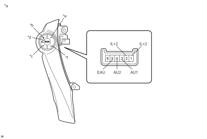
Measure the resistance according to the value(s) in the table below.
E256150E02
1.469,1.271 1.156,0.958 false 1.469,1.583 1.156,1.896 false 1.563,1.396 1.115,1.302 false 1.792,1.26 2.208,0.625 false 1.802,1.583 2.25,1.917 false 3.896,2.073 3.563,2.406 false 4.896,1.604 4.552,1.938 false 4.229,2.073 4.573,2.406 false 4.042,1.604 4.375,1.938 false 4.052,2.073 4.052,2.406 false 0.146,0.115 0.625,0.281 0.479,0.167 10 false *a 1.031,0.792 1.385,0.958 0.354,0.167 10 false *b 1.021,1.865 1.375,2.031 0.354,0.167 10 false *c 0.948,1.208 1.302,1.375 0.354,0.167 10 false *d 2.177,0.469 2.531,0.635 0.354,0.167 10 false *e 2.26,1.917 2.615,2.083 0.354,0.167 10 false *f 3.365,2.427 3.719,2.594 0.354,0.167 10 false EAU 3.927,2.427 4.281,2.594 0.354,0.167 10 false AU2 4.51,2.427 4.865,2.594 0.354,0.167 10 false AU1 3.813,1.438 4.167,1.604 0.354,0.167 10 false IL+2 4.823,1.438 5.177,1.604 0.354,0.167 10 false IL+2

Standard Resistance:
Tester Connection Condition Specified Condition
1 (IL+2) - 2 (IL+2) No switch pushed Below 1 Ω
3 (AU1) - 5 (EAU) No switch pushed 95 to 105 kΩ
Seek+ switch pushed Below 2.5 Ω
Seek- switch pushed 323 to 335 Ω
Volume+ switch pushed 980 to 1020 Ω
Volume- switch pushed 3048 to 3172 Ω
4 (AU2) - 5 (EAU) No switch pushed 95 to 105 kΩ
MODE switch pushed Below 2.5 Ω


HINT:

If the result is not as specified, replace the steering pad switch LH.


Text in Illustration
*a Component without harness connected
(Steering Pad Switch LH)
*b Volume+
*c Volume- *d MODE
*e Seek+ *f Seek-


b.

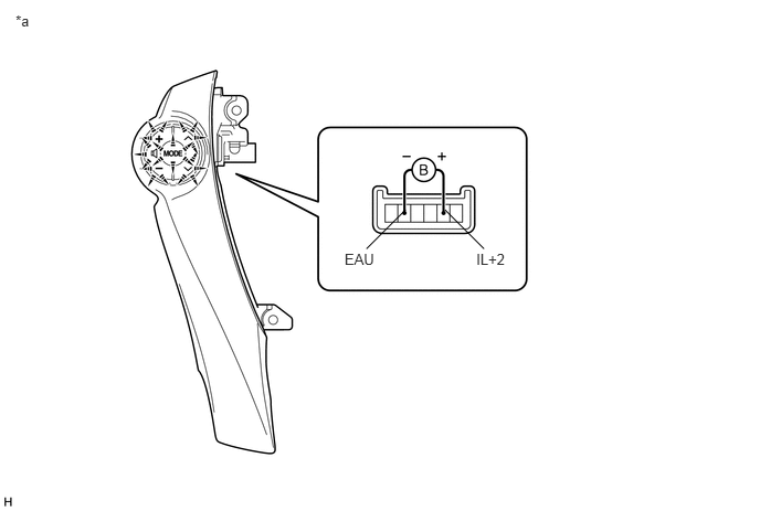
Check the illumination.

E256151E02
0.147,0.113 0.632,0.282 0.485,0.169 10 *a 4.491,2.366 4.812,2.535 0.321,0.169 10 IL+2 3.249,2.366 3.570,2.535 0.321,0.169 10 EAU 4.195,1.979 4.565,2.348 false 3.825,1.979 3.456,2.348 false

i.

Connect an auxiliary battery positive (+) lead to terminal IL+2 and a negative (-) lead to terminal EAU of the steering pad switch LH connector.


ii.

Check that the switch illumination comes on.

OK:

Steering pad switch illumination comes on.


HINT:

If the result is not as specified, replace the steering pad switch LH.


Text in Illustration
*a Component without harness connected
(Steering Pad Switch LH)
- -


Hide 2.INSPECT STEERING PAD SWITCH RH

a.

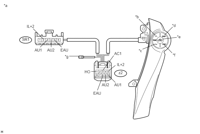
Measure the resistance according to the value(s) in the table below.
U183748E02
1.688,1.448 1.438,1.698 false 1.958,1.448 2.208,1.698 false 1.833,1.448 1.833,1.698 false 3.688,2.719 3.49,3.25 false 4.135,2.354 3.896,2.542 false 3.885,2.719 4.135,2.969 false 3.781,2.719 3.781,2.969 false 1.552,1.406 1.188,1.031 false 3.677,2.542 4.073,2 false 5.563,1.271 4.979,0.688 false 5.563,1.583 5.104,1.771 false 5.896,1.26 6.188,0.969 false 5.885,1.615 6.167,1.906 false 5.823,1.406 6.333,1.344 false 2.823,2.021 2.479,2.021 false 3.448,2.573 3.271,2.573 false 0.135,0.115 0.708,0.281 0.573,0.167 10 false *a 2.323,1.948 2.677,2.115 0.354,0.167 10 false *g 4.844,0.521 5.198,0.688 0.354,0.167 10 false *b 4.969,1.74 5.323,1.906 0.354,0.167 10 false *c 6.167,0.833 6.521,1 0.354,0.167 10 false *d 6.344,1.24 6.698,1.406 0.354,0.167 10 false *e 6.188,1.896 6.542,2.063 0.354,0.167 10 false *f 0.792,1.333 1.146,1.5 0.354,0.167 10 false SR1 0.958,0.865 1.313,1.031 0.354,0.167 10 false IL+2 4.188,2.24 4.542,2.406 0.354,0.167 10 false IL+2 1.24,1.719 1.594,1.885 0.354,0.167 10 false AU1 1.688,1.719 2.042,1.885 0.354,0.167 10 false AU2 2.167,1.719 2.521,1.885 0.354,0.167 10 false EAU 4.25,2.531 4.604,2.698 0.354,0.167 10 false z2 3.344,3.271 3.698,3.438 0.354,0.167 10 false EAU 3.031,2.5 3.385,2.667 0.354,0.167 10 false HO 3.646,2.969 4,3.135 0.354,0.167 10 false AU2 4.094,2.969 4.448,3.135 0.354,0.167 10 false AU1 4.094,1.844 4.448,2.01 0.354,0.167 10 false AC1

Standard Resistance:
Tester Connection Condition Specified Condition
z9-1 (HO) - Terminal-A Always Below 1 Ω
z9-3 (AC1) - z9-8 (EAU) No switch pushed 95 to 105 kΩ
R/F switch pushed 323 to 335 Ω
TEMP+ switch pushed 980 to 1020 Ω
TEMP- switch pushed 3048 to 3172 Ω
SR1-2 (IL+2) - z2-5 (IL+2) Always Below 1 Ω
SR1-3 (AU1) - z2-10 (AU1) Always Below 1 Ω
SR1-4 (AU2) - z2-9 (AU2) Always Below 1 Ω
SR1-5 (EAU) - z2-8 (EAU) Always Below 1 Ω


HINT:

If the result is not as specified, replace the steering pad switch RH.


Text in Illustration
*a Component without harness connected
(Steering Pad Switch RH)
*b TEMP+
*c TEMP- *d DISP
*e R/F *f TRIP
*g Terminal-A - -


b.

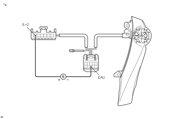
Check the illumination.

E256153E02
1.427,1.438 1.083,1.094 false 4.01,3.042 3.677,2.698 false 0.135,0.104 0.594,0.281 0.458,0.177 10 false *a 3.969,3.052 4.281,3.229 0.313,0.177 10 false EAU 0.896,0.906 1.208,1.083 0.313,0.177 10 false IL+2

i.

Connect an auxiliary battery positive (+) lead to terminal IL+2 and a negative (-) lead to terminal EAU of the steering pad switch RH connector.


ii.

Check that the switch illumination comes on.

OK:

Steering pad switch illumination comes on.


HINT:

If the result is not as specified, replace the steering pad switch RH.


Text in Illustration
*a Component without harness connected
(Steering Pad Switch RH)
- -