Home › Audio / Visual / Telematics › AUDIO / VIDEO › AUDIO AND VISUAL SYSTEM
RM2170E _56 Audio / Visual / Telematics _057029 AUDIO / VIDEO _0278060 AUDIO AND VISUAL SYSTEM J

AUDIO / VIDEO  AUDIO AND VISUAL SYSTEM  Microphone Circuit between Microphone and Radio Receiver  


DESCRIPTION

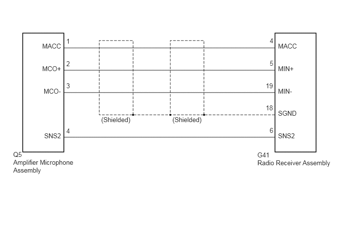
Using this circuit, the radio receiver assembly sends power to the amplifier microphone assembly, and the amplifier microphone assembly sends microphone signals to the radio receiver assembly.

WIRING DIAGRAM
E204785E15
0.281,3.198 0.563,3.344 0.281,0.146 10 false Q5 0.281,3.365 1.635,3.74 1.354,0.375 10 false Amplifier Microphone Assembly 5.458,3.208 5.823,3.354 0.365,0.146 10 false G41 5.458,3.375 7.073,3.552 1.615,0.177 10 false Radio Receiver Assembly 5.896,1.375 6.281,1.521 0.385,0.146 10 false MIN+ 5.896,0.896 6.323,1.042 0.427,0.146 10 false MACC 5.635,1.74 5.813,1.885 0.177,0.146 10 false 19 5.719,1.26 5.823,1.406 0.104,0.146 10 false 5 5.719,0.781 5.823,0.927 0.104,0.146 10 false 4 5.635,2.208 5.813,2.354 0.177,0.146 10 false 18 5.719,2.688 5.823,2.833 0.104,0.146 10 false 6 5.896,1.854 6.281,2 0.385,0.146 10 false MIN- 5.896,2.323 6.323,2.469 0.427,0.146 10 false SGND 5.896,2.802 6.292,2.948 0.396,0.146 10 false SNS2 1.406,2.698 1.583,2.844 0.177,0.146 10 false 4 1.406,0.792 1.583,0.938 0.177,0.146 10 false 1 1.406,1.271 1.583,1.417 0.177,0.146 10 false 2 1.406,1.74 1.583,1.885 0.177,0.146 10 false 3 0.938,2.802 1.323,2.948 0.385,0.146 10 false SNS2 0.896,0.896 1.323,1.042 0.427,0.146 10 false MACC 0.896,1.375 1.323,1.521 0.427,0.146 10 false MCO+ 0.927,1.854 1.323,2 0.396,0.146 10 false MCO- 2.146,2.458 2.802,2.646 0.656,0.188 10 false (Shielded) 3.656,2.458 4.313,2.729 0.656,0.271 10 false (Shielded)

PROCEDURE

1.CHECK HARNESS AND CONNECTOR (RADIO RECEIVER ASSEMBLY - AMPLIFIER MICROPHONE ASSEMBLY)
a.

Disconnect the radio receiver assembly and amplifier microphone assembly connectors.


b.

Measure the resistance according to the value(s) in the table below.

Standard Resistance:
Tester Connection Condition Specified Condition
G41-6 (SNS2) - Q5-4 (SNS2) Always Below 1 Ω
G41-4 (MACC) - Q5-1 (MACC) Always Below 1 Ω
G41-5 (MIN+) - Q5-2 (MCO+) Always Below 1 Ω
G41-19 (MIN-) - Q5-3 (MCO-) Always Below 1 Ω
G41-6 (SNS2) - Body ground Always 10 kΩ or higher
G41-4 (MACC) - Body ground Always 10 kΩ or higher
G41-5 (MIN+) - Body ground Always 10 kΩ or higher
G41-19 (MIN-) - Body ground Always 10 kΩ or higher
G41-18 (SGND) - Body ground Always 10 kΩ or higher


OK

2.INSPECT RADIO RECEIVER ASSEMBLY

NG

REPAIR OR REPLACE HARNESS OR CONNECTOR

2.INSPECT RADIO RECEIVER ASSEMBLY
a.

Reconnect the radio receiver assembly connector.


b.

Reconnect the amplifier microphone assembly connector.
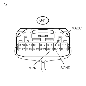

c.
U183703E02
2.229,2 2.573,2.604 false 2.073,1.99 1.323,2.615 false 2.25,1.75 2.833,1.198 false 0.156,0.083 0.365,0.302 0.208,0.219 10 false *a 1.573,0.729 1.938,0.927 0.365,0.198 10 false G41 2.417,2.625 2.833,2.823 0.417,0.198 10 false SGND 2.865,1.042 3.313,1.24 0.448,0.198 10 false MACC 1.146,2.635 1.521,2.833 0.375,0.198 10 false MIN-

Measure the voltage according to the value(s) in the table below.

Standard Voltage:
Tester Connection Condition Specified Condition
G41-4 (MACC) - Body ground Power switch on (ACC) 4 to 6 V


d.

Measure the resistance according to the value(s) in the table below.

Standard Resistance:
Tester Connection Condition Specified Condition
G41-18 (SGND) - Body ground Always Below 1 Ω
G41-19 (MIN-) - Body ground Always Below 1 Ω


Text in Illustration
*a Component with harness connected
(Radio Receiver Assembly)


OK

3.INSPECT AMPLIFIER MICROPHONE ASSEMBLY

NG

REPLACE RADIO RECEIVER ASSEMBLY

3.INSPECT AMPLIFIER MICROPHONE ASSEMBLY
a.

Disconnect the amplifier microphone assembly connector.
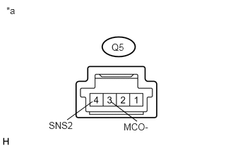

b.
U183728E02
1.365,1.5 0.99,1.771 false 1.646,1.51 2.021,1.792 false 1.646,0.615 1.854,0.792 0.208,0.177 10 false Q5 0.094,0.073 0.292,0.271 0.198,0.198 10 false *a 0.719,1.771 1.135,1.969 0.417,0.198 10 false SNS2 1.823,1.792 2.25,1.99 0.427,0.198 10 false MCO-

Measure the resistance according to the value(s) in the table below.

Standard Resistance:
Tester Connection Condition Specified Condition
Q5-3 (MCO-) - Q5-4 (SNS2) Always Below 1 Ω


Text in Illustration
*a Component without harness connected
(Amplifier Microphone Assembly)


OK

4.INSPECT AMPLIFIER MICROPHONE ASSEMBLY

NG

REPLACE AMPLIFIER MICROPHONE ASSEMBLY

4.INSPECT AMPLIFIER MICROPHONE ASSEMBLY
a.

Reconnect the radio receiver assembly connector.
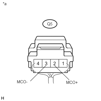

b.
U183729E02
1.563,2.229 1.031,2.76 false 1.854,2.229 2.354,2.719 false 1.604,0.729 1.875,0.906 0.271,0.177 10 false Q5 0.094,0.042 0.292,0.24 0.198,0.198 10 false *a 0.573,2.698 1.031,2.896 0.458,0.198 10 false MCO- 2.25,2.719 2.677,2.917 0.427,0.198 10 false MCO+

Reconnect the amplifier microphone assembly connector.


c.

Turn the power switch to ACC.


d.

Connect an oscilloscope to terminals 2 (MCO+) and 3 (MCO-) of the amplifier microphone assembly connector.


e.

Check the waveform of the amplifier microphone assembly using the oscilloscope.

Result:
Result Proceed to
A waveform synchronized with the voice input to the amplifier microphone assembly is output A
A waveform synchronized with the voice input to the amplifier microphone assembly is not output B


Text in Illustration
*a Component with harness connected
(Amplifier Microphone Assembly)


A

END

B

REPLACE AMPLIFIER MICROPHONE ASSEMBLY