RM2170E
_57
Power Source / Network
_057033
NETWORKING
_0278068
CAN COMMUNICATION SYSTEM
U
NETWORKING CAN COMMUNICATION SYSTEM SYSTEM DIAGRAM
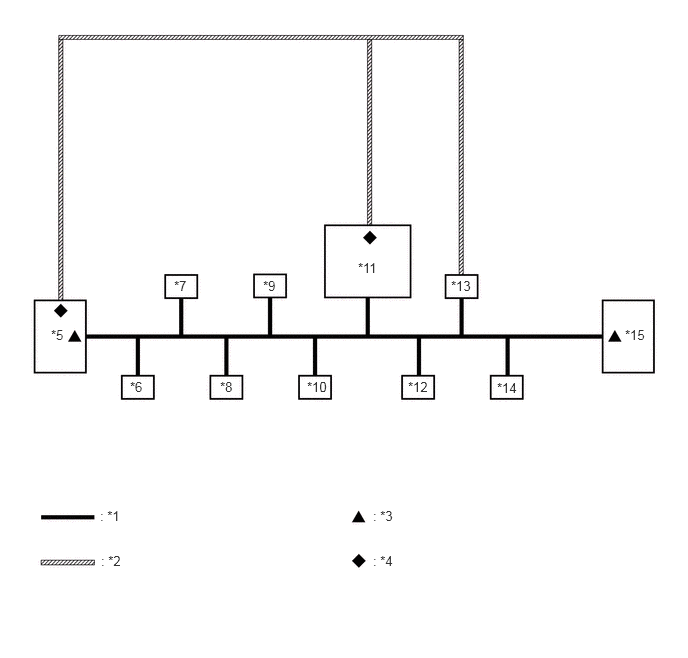
OVERALL CAN BUS DIAGRAM (for LHD)
a.
Control system CAN is composed of 2 buses.
1.042,5.292 1.333,5.49
0.292,0.198
10
false
: *1
1.052,5.76 1.344,5.958
0.292,0.198
10
false
: *2
3.885,5.292 4.177,5.49
0.292,0.198
10
false
: *3
3.885,5.76 4.177,5.958
0.292,0.198
10
false
: *4
0.531,3.406 0.729,3.604
0.198,0.198
10
false
*5
1.813,2.896 2.01,3.094
0.198,0.198
10
false
*7
2.74,2.896 2.938,3.094
0.198,0.198
10
false
*9
1.354,3.948 1.552,4.146
0.198,0.198
10
false
*6
2.292,3.948 2.49,4.146
0.198,0.198
10
false
*8
3.198,3.948 3.438,4.146
0.24,0.198
10
false
*10
4.25,3.948 4.615,4.146
0.365,0.198
10
false
*12
3.729,2.708 4.031,2.906
0.302,0.198
10
false
*11
4.698,2.896 5,3.094
0.302,0.198
10
false
*13
5.177,3.958 5.51,4.156
0.333,0.198
10
false
*14
6.51,3.406 6.844,3.604
0.333,0.198
10
false
*15
| *1 | V Bus | *2 | Sub Bus 15 |
| *3 | V Bus Terminating Resistor | *4 | Sub Bus 15 Terminating Resistor |
| *5 | ECM
(for V Bus and Sub Bus 15) |
*6 | Main Body ECU (Multiplex Network Body ECU)
(for V Bus) |
| *7 | Airbag Sensor Assembly
(for V Bus) |
*8 | Spiral Cable with Sensor Sub-assembly (Steering Sensor)
(for V Bus) |
| *9 | Power Steering ECU Assembly
(for V Bus) |
*10 | Air Conditioning Amplifier Assembly
(for V Bus) |
| *11 | Power Management Control ECU
(for V Bus and Sub Bus 15) |
*12 | Smart Key ECU Assembly (Certification ECU)
(for V Bus) |
| *13 | Brake Booster with Master Cylinder Assembly (Skid Control ECU)
(for V Bus and Sub Bus 15) |
*14 | DLC3
(for V Bus) |
| *15 | Combination Meter Assembly
(for V Bus) |
- | - |
- HINT:
-
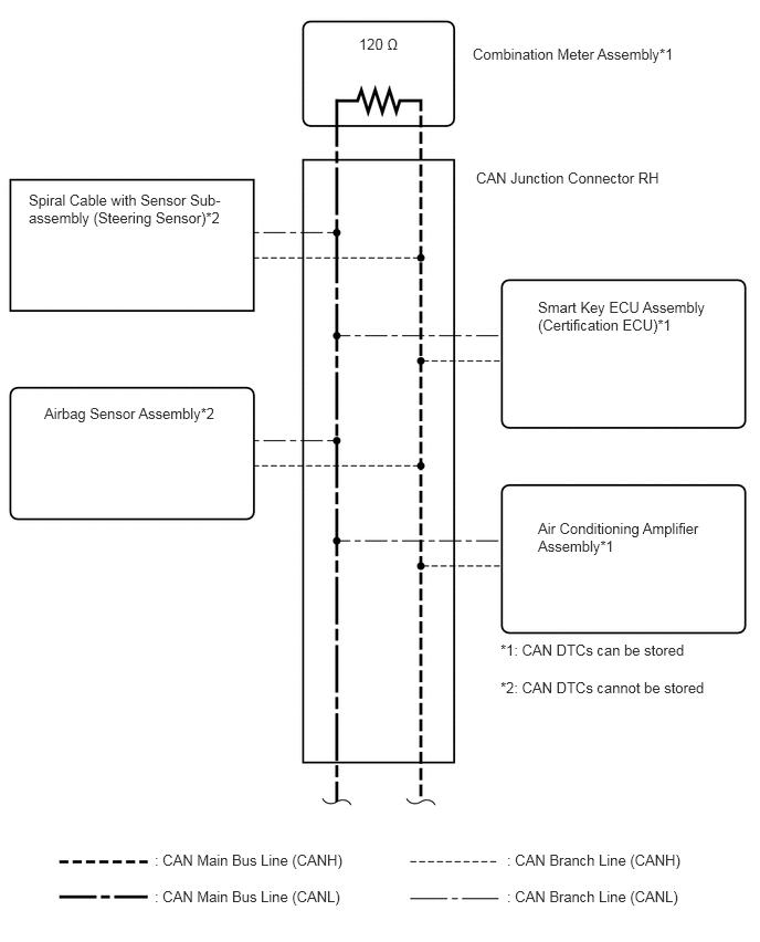
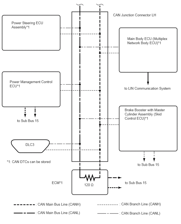
Refer to the following bus wiring diagrams for details.
V BUS (for LHD)
4.458,0.427 6.458,0.875
2,0.448
10
false
Combination Meter Assembly*1
3.385,0.333 3.813,0.51
0.427,0.177
10
false
120 Ω
1.458,8.021 3.417,8.344
1.958,0.323
10
false
: CAN Main Bus Line (CANH)
4.781,8.021 6.49,8.344
1.708,0.323
10
false
: CAN Branch Line (CANH)
4.781,8.365 6.469,8.688
1.688,0.323
10
false
: CAN Branch Line (CANL)
1.458,8.365 3.417,8.688
1.958,0.323
10
false
: CAN Main Bus Line (CANL)
4.719,6.042 6.552,6.24
1.833,0.198
10
false
*1: CAN DTCs can be stored
4.719,6.396 6.76,6.594
2.042,0.198
10
false
*2: CAN DTCs cannot be stored
0.271,1.802 2.333,2.188
2.063,0.385
10
false
Spiral Cable with Sensor Sub-assembly (Steering Sensor)*2
4.49,1.594 6.458,1.771
1.969,0.177
10
false
CAN Junction Connector RH
0.417,3.813 2.135,4
1.719,0.188
10
false
Airbag Sensor Assembly*2
5.073,4.896 6.698,5.25
1.625,0.354
10
false
Air Conditioning Amplifier Assembly*1
5.073,2.813 6.76,3.208
1.688,0.396
10
false
Smart Key ECU Assembly (Certification ECU)*1
5.042,1.448 6.729,1.896
1.688,0.448
10
false
Main Body ECU (Multiplex Network Body ECU)*1
0.385,3.156 2.177,3.604
1.792,0.448
10
false
Power Management Control ECU*1
1.01,5.646 1.448,5.813
0.438,0.167
10
false
DLC3
4.927,3.417 6.875,3.656
1.948,0.24
10
false
to LIN Communication System
4.479,0.51 6.448,0.698
1.969,0.188
10
false
CAN Junction Connector LH
4.938,4.271 6.865,4.938
1.927,0.667
10
false
Brake Booster with Master Cylinder Assembly (Skid Control ECU)*1
0.271,6.323 2.104,6.521
1.833,0.198
10
false
*1: CAN DTCs can be stored
5.448,6.438 6.469,6.625
1.021,0.188
10
false
to Sub Bus 15
3.333,7.24 3.781,7.417
0.448,0.177
10
false
120 Ω
2.052,7.156 2.646,7.438
0.594,0.281
10
false
ECM*1
1.417,8.01 3.375,8.333
1.958,0.323
10
false
: CAN Main Bus Line (CANH)
4.729,8 6.438,8.323
1.708,0.323
10
false
: CAN Branch Line (CANH)
4.729,8.365 6.417,8.688
1.688,0.323
10
false
: CAN Branch Line (CANL)
1.417,8.344 3.375,8.667
1.958,0.323
10
false
: CAN Main Bus Line (CANL)
0.458,0.823 2.063,1.417
1.604,0.594
10
false
Power Steering ECU Assembly*1
4.948,7.156 5.969,7.344
1.021,0.188
10
false
to Sub Bus 15
0.677,4.698 1.698,4.885
1.021,0.188
10
false
to Sub Bus 15
- HINT:
-
The CAN communication system connects to other network via ECUs that function as a gateway (See page Power Source / Network>NETWORKING>LIN COMMUNICATION SYSTEM>SYSTEM DIAGRAM).
OVERALL CAN BUS DIAGRAM (for RHD)
a.
Control system CAN is composed of 2 buses.
1.042,5.292 1.333,5.49
0.292,0.198
10
false
: *1
1.052,5.76 1.344,5.958
0.292,0.198
10
false
: *2
3.885,5.292 4.177,5.49
0.292,0.198
10
false
: *3
3.885,5.76 4.177,5.958
0.292,0.198
10
false
: *4
0.531,3.406 0.729,3.604
0.198,0.198
10
false
*5
1.813,2.896 2.01,3.094
0.198,0.198
10
false
*7
2.74,2.896 2.938,3.094
0.198,0.198
10
false
*9
1.354,3.948 1.552,4.146
0.198,0.198
10
false
*6
2.292,3.948 2.49,4.146
0.198,0.198
10
false
*8
3.198,3.948 3.438,4.146
0.24,0.198
10
false
*10
4.25,3.948 4.615,4.146
0.365,0.198
10
false
*12
3.729,2.708 4.031,2.906
0.302,0.198
10
false
*11
4.698,2.896 5,3.094
0.302,0.198
10
false
*13
5.177,3.958 5.51,4.156
0.333,0.198
10
false
*14
6.51,3.406 6.844,3.604
0.333,0.198
10
false
*15
| *1 | V Bus | *2 | Sub Bus 15 |
| *3 | V Bus Terminating Resistor | *4 | Sub Bus 15 Terminating Resistor |
| *5 | ECM
(for V Bus and Sub Bus 15) |
*6 | Main Body ECU (Multiplex Network Body ECU)
(for V Bus) |
| *7 | Airbag Sensor Assembly
(for V Bus) |
*8 | Spiral Cable with Sensor Sub-assembly (Steering Sensor)
(for V Bus) |
| *9 | Power Steering ECU Assembly
(for V Bus) |
*10 | Air Conditioning Amplifier Assembly
(for V Bus) |
| *11 | Power Management Control ECU
(for V Bus and Sub Bus 15) |
*12 | Smart Key ECU Assembly (Certification ECU)
(for V Bus) |
| *13 | Brake Booster with Master Cylinder Assembly (Skid Control ECU)
(for V Bus and Sub Bus 15) |
*14 | DLC3
(for V Bus) |
| *15 | Combination Meter Assembly
(for V Bus) |
- | - |
- HINT:
-
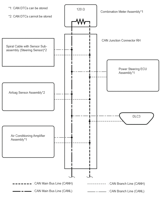
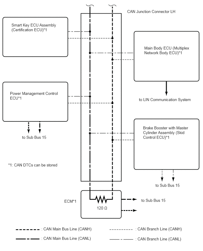
Refer to the following bus wiring diagrams for details.
V BUS (for RHD)
4.448,0.427 6.448,0.875
2,0.448
10
false
Combination Meter Assembly*1
3.385,0.323 3.813,0.5
0.427,0.177
10
false
120 Ω
5.865,5.052 6.302,5.219
0.438,0.167
10
false
DLC3
1.448,8.01 3.406,8.333
1.958,0.323
10
false
: CAN Main Bus Line (CANH)
4.771,8.021 6.479,8.344
1.708,0.323
10
false
: CAN Branch Line (CANH)
4.771,8.354 6.458,8.677
1.688,0.323
10
false
: CAN Branch Line (CANL)
1.448,8.344 3.406,8.667
1.958,0.323
10
false
: CAN Main Bus Line (CANL)
0.375,0.271 2.208,0.469
1.833,0.198
10
false
*1: CAN DTCs can be stored
0.375,0.635 2.417,0.833
2.042,0.198
10
false
*2: CAN DTCs cannot be stored
0.271,1.958 2.375,2.604
2.104,0.646
10
false
Spiral Cable with Sensor Sub-assembly (Steering Sensor)*2
4.5,1.698 6.469,1.875
1.969,0.177
10
false
CAN Junction Connector RH
0.385,4 2.365,4.313
1.979,0.313
10
false
Airbag Sensor Assembly*2
0.479,5.906 2.104,6.26
1.625,0.354
10
false
Air Conditioning Amplifier Assembly*1
5.25,2.958 6.854,3.552
1.604,0.594
10
false
Power Steering ECU Assembly*1
5.094,1.615 6.781,2.063
1.688,0.448
10
false
Main Body ECU (Multiplex Network Body ECU)*1
0.354,3.219 2.146,3.667
1.792,0.448
10
false
Power Management Control ECU*1
4.906,3.438 6.875,3.677
1.969,0.24
10
false
to LIN Communication System
4.49,0.323 6.458,0.646
1.969,0.323
10
false
CAN Junction Connector LH
5.052,4.438 6.979,5.104
1.927,0.667
10
false
Brake Booster with Master Cylinder Assembly (Skid Control ECU)*1
0.292,5.75 2.125,5.948
1.833,0.198
10
false
*1: CAN DTCs can be stored
4.99,7 6.01,7.188
1.021,0.188
10
false
to Sub Bus 15
5.49,6.469 6.51,6.656
1.021,0.188
10
false
to Sub Bus 15
3.417,7.271 3.865,7.448
0.448,0.177
10
false
120 Ω
2.271,7.031 2.865,7.188
0.594,0.156
10
false
ECM*1
0.781,4.771 1.729,4.927
0.948,0.156
10
false
to Sub Bus 15
1.458,8.01 3.417,8.333
1.958,0.323
10
false
: CAN Main Bus Line (CANH)
4.781,8.01 6.49,8.333
1.708,0.323
10
false
: CAN Branch Line (CANH)
4.781,8.365 6.469,8.688
1.688,0.323
10
false
: CAN Branch Line (CANL)
1.458,8.344 3.417,8.667
1.958,0.323
10
false
: CAN Main Bus Line (CANL)
0.406,0.802 2.094,1.198
1.688,0.396
10
false
Smart Key ECU Assembly (Certification ECU)*1
- HINT:
-
The CAN communication system connects to other network via ECUs that function as a gateway (See page Power Source / Network>NETWORKING>LIN COMMUNICATION SYSTEM>SYSTEM DIAGRAM).
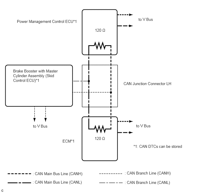
SUB BUS 15
0.604,0.677 2.896,1.125
2.292,0.448
10
false
Power Management Control ECU*1
3.385,0.99 3.813,1.167
0.427,0.177
10
false
120 Ω
3.375,4.833 3.802,5.01
0.427,0.177
10
false
120 Ω
2.229,4.927 2.906,5.094
0.677,0.167
10
false
ECM*1
0.469,2.438 2.125,3.073
1.656,0.635
10
false
Brake Booster with Master Cylinder Assembly (Skid Control ECU)*1
1.167,6.083 3.125,6.406
1.958,0.323
10
false
: CAN Main Bus Line (CANH)
4.448,6.063 6.156,6.385
1.708,0.323
10
false
: CAN Branch Line (CANH)
4.448,6.396 6.135,6.719
1.688,0.323
10
false
: CAN Branch Line (CANL)
1.167,6.385 3.125,6.708
1.958,0.323
10
false
: CAN Main Bus Line (CANL)
4.406,2.885 6.646,3.281
2.24,0.396
10
false
CAN Junction Connector LH
4.76,5.115 6.594,5.313
1.833,0.198
10
false
*1: CAN DTCs can be stored
1.177,4.396 2.031,4.583
0.854,0.188
10
false
to V Bus
4.938,0.604 5.792,0.792
0.854,0.188
10
false
to V Bus
4.854,4.385 5.708,4.573
0.854,0.188
10
false
to V Bus