DOOR LOCK WIRELESS DOOR LOCK CONTROL SYSTEM TERMINALS OF ECU
CHECK INSTRUMENT PANEL JUNCTION BLOCK ASSEMBLY AND MAIN BODY ECU (MULTIPLEX NETWORK BODY ECU)
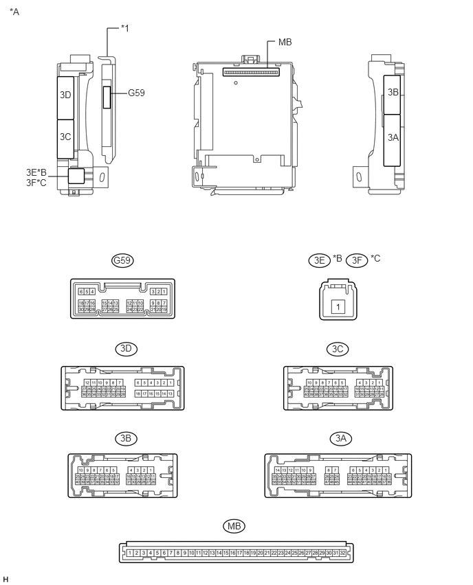
| *A | Main body ECU (multiplex network body ECU) with 1 connector | *B | for LHD |
| *C | for RHD | - | - |
| *1 | Main body ECU (multiplex network body ECU) | - | - |
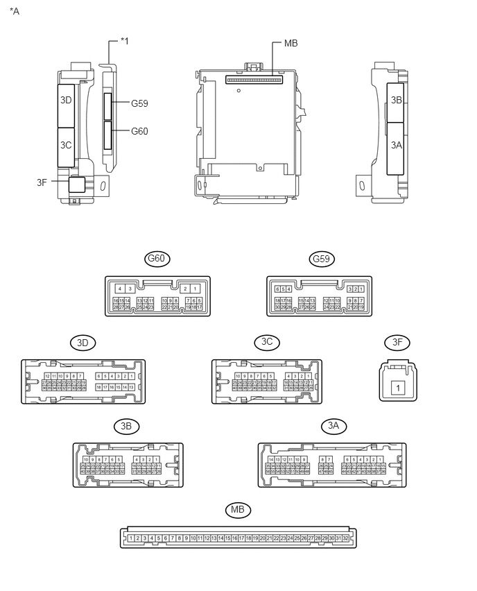
| *A | Main body ECU (multiplex network body ECU) with 2 connectors | *B | for LHD |
| *C | for RHD | - | - |
| *1 | Main body ECU (multiplex network body ECU) | - | - |
Disconnect the MB main body ECU (multiplex network body ECU) connector.
Measure the voltage and resistance according to the value(s) in the table below.
- HINT:
-
Measure the values on the wire harness side with the connectors disconnected.
| Tester Connection | Wiring Color | Terminal Description | Condition | Specified Condition |
|---|---|---|---|---|
| MB-11 (GND1) - Body ground | - | Ground | Always | Below 1 Ω |
| MB-30 (BECU) - Body ground | - | Auxiliary battery power supply | Power switch off | 11 to 14 V |
| MB-29 (ACC) - Body ground | - | ACC power supply | Power switch on (ACC) | 11 to 14 V |
| MB-29 (ACC) - Body ground | - | ACC power supply | Power switch off | Below 1 V |
| MB-32 (IG) - Body ground | - | IG power supply | Power switch on (IG) | 11 to 14 V |
| MB-32 (IG) - Body ground | - | IG power supply | Power switch off | Below 1 V |
Reconnect the MB main body ECU (multiplex network body ECU) connector.
Measure the voltage according to the value(s) in the table below.
| Tester Connection | Wiring Color | Terminal Description | Condition | Specified Condition |
|---|---|---|---|---|
| 3B-3 (ACT-) - Body ground | R - Body ground | Door lock motor unlock drive output (all doors) | Door control switch (power window regulator master switch assembly) or driver door key cylinder off | Below 1 V |
| 3B-3 (ACT-) - Body ground | R - Body ground | Door lock motor unlock drive output (all doors) | Door control switch (power window regulator master switch assembly) or driver door key cylinder unlocked | 11 to 14 V |
| 3B-1 (ACT+) - Body ground | Y - Body ground | Door lock motor lock drive output (all doors) | Door control switch (power window regulator master switch assembly) or driver door key cylinder off | Below 1 V |
| 3B-1 (ACT+) - Body ground | Y - Body ground | Door lock motor lock drive output (all doors) | Door control switch (power window regulator master switch assembly) or driver door key cylinder locked | 11 to 14 V |
| 3D-36 (FLCY) - Body ground | R - Body ground | Front door LH courtesy light switch input | Front door LH open | Below 1 V |
| 3D-36 (FLCY) - Body ground | R - Body ground | Front door LH courtesy light switch input | Front door LH closed | Pulse generation |
| G59-19 (FRCY) - Body ground | R - Body ground | Front door RH courtesy light switch input | Front door RH open | Below 1 V |
| G59-19 (FRCY) - Body ground | R - Body ground | Front door RH courtesy light switch input | Front door RH closed | Pulse generation |
| G59-24 (LCTY) - Body ground | L - Body ground | Rear door LH courtesy light switch input | Rear door LH open | Below 1 V |
| G59-24 (LCTY) - Body ground | L - Body ground | Rear door LH courtesy light switch input | Rear door LH closed | Pulse generation |
| G59-6 (RCTY) - Body ground | G - Body ground | Rear door RH courtesy light switch input | Rear door RH open | Below 1 V |
| G59-6 (RCTY) - Body ground | G - Body ground | Rear door RH courtesy light switch input | Rear door RH closed | Pulse generation |
| G59-7 (LSFL) - Body ground | L - Body ground | Front door LH unlock detection switch input | Front door LH unlocked | Below 1 V |
| G59-7 (LSFL) - Body ground | L - Body ground | Front door LH unlock detection switch input | Front door LH locked | Pulse generation |
| G59-18 (LSFR) - Body ground | L - Body ground | Front door RH unlock detection switch input | Front door RH unlocked | Below 1 V |
| G59-18 (LSFR) - Body ground | L - Body ground | Front door RH unlock detection switch input | Front door RH locked | Pulse generation |
| 3D-25 (LSR) - Body ground | V - Body ground | Rear door RH unlock detection switch input | Rear door RH unlocked | Below 1 V |
| 3D-25 (LSR) - Body ground | V - Body ground | Rear door RH unlock detection switch input | Rear door RH locked | Pulse generation |
| 3D-24 (LSR) - Body ground | Y - Body ground | Rear door LH unlock detection switch input | Rear door LH unlocked | Below 1 V |
| 3D-24 (LSR) - Body ground | Y - Body ground | Rear door LH unlock detection switch input | Rear door LH locked | Pulse generation |
| 3C-34 (BZR) - Body ground | B - Body ground | Wireless door lock buzzer signal | Wireless door lock buzzer off | Below 1 V |
| 3C-34 (BZR) - Body ground | B - Body ground | Wireless door lock buzzer signal | Wireless door lock buzzer on | Pulse generation |
CHECK CERTIFICATION ECU (SMART KEY ECU ASSEMBLY)
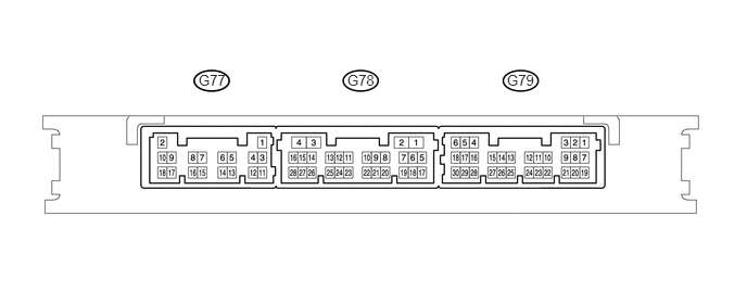
Disconnect the G77 certification ECU (smart key ECU assembly) connector.
Measure the resistance and voltage according to the value(s) in the table below.
- HINT:
-
Measure the values on the wire harness side with the connectors disconnected.
| Tester Connection | Wiring Color | Terminal Description | Condition | Specified Condition |
|---|---|---|---|---|
| G77-11 (E) - Body ground | W-B - Body ground | Ground | Always | Below 1 Ω |
| G77-2 (+B) - Body ground | B - Body ground | Auxiliary battery power supply | Always | 11 to 14 V |
| G77-10 (CUTB) - Body ground | L - Body ground | Dark current cut fuse pin input signal | Always | 11 to 14 V |
Reconnect the G77 certification ECU (smart key ECU assembly) connectors.
Measure the voltage according to the value(s) in the table below.
| Tester Connection | Wiring Color | Terminal Description | Condition | Specified Condition |
|---|---|---|---|---|
| G79-5 (IG) - G77-11 (E) | V - W-B | IG power supply | Power switch on (IG) | 11 to 14 V |
| Power switch off | Below 1 V | |||
| G78-19 (RSSI) - G77-11 (E) | R - W-B*1
P - W-B*2 |
Communication channel switching circuit | Procedure:
1.
Power switch off 2.
All doors closed 3.
Lock or unlock switch of electrical key transmitter sub-assembly not pressed → pressed |
11 to 14 V → Below 2 V |
| G78-17 (RDAS) - G77-11 (E) | LG - W-B | Door control receiver verifies data received from electrical key transmitter sub-assembly. Door control receiver sends data from electrical key transmitter sub-assembly to certification ECU (smart key ECU assembly) (Door control receiver intermittently grounds 12 V signal from certification ECU (smart key ECU assembly)). | Procedure:
1.
Power switch off 2.
All doors locked 3.
Electrical key transmitter sub-assembly not inside vehicle 4.
Electrical key transmitter sub-assembly brought outside detection area but kept inside wireless function operational area 5.
Lock or unlock switch of electrical key transmitter sub-assembly not pressed → pressed |
Pulse generation
(See waveform 1) |
| G78-5 (RCO) - G77-11 (E) | L - W-B | Output to door control receiver (Power supply for door control receiver . Certification ECU (smart key ECU assembly) outputs 5 V when receiver starts operating.) | Procedure:
1.
Power switch off 2.
Electrical key transmitter sub-assembly brought outside detection area but kept inside wireless function operational area 3.
Lock or unlock switch of electrical key transmitter sub-assembly not pressed → pressed |
Below 1 V → 4.5 to 5.5 V |
*1: for LHD
*2: for RHD
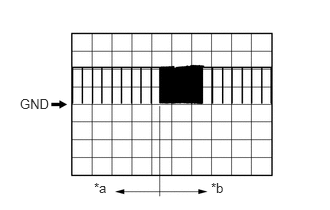
Using an oscilloscope, check waveform 1.
- HINT:
-
The oscilloscope waveform shown in the illustration is an example for reference only. Noise, chattering, etc. are not shown.
| Item | Content |
|---|---|
| Tester connection | G78-17 (RDAS) - G77-11 (E) |
| Tool setting | 5 V/DIV., 500 ms/DIV. |
| Condition | Procedure:
1.
Power switch off 2.
All doors locked 3.
Electrical key transmitter sub-assembly not inside vehicle 4.
Electrical key transmitter sub-assembly brought outside detection area but kept inside wireless function operational area 5.
Lock or unlock switch of electrical key transmitter sub-assembly not pressed → pressed |
| *a | Before lock or unlock switch of electrical key transmitter sub-assembly pressed |
| *b | After lock or unlock switch of electrical key transmitter sub-assembly pressed |
CHECK DOOR CONTROL RECEIVER ASSEMBLY

Disconnect the M15 door control receiver connector.
Measure the resistance and voltage according to the value(s) in the table below.
- HINT:
-
Measure the values on the wire harness side with the connectors disconnected.
| Tester Connection | Wiring Color | Terminal Description | Condition | Specified Condition |
|---|---|---|---|---|
| M15-1 (GND) - Body ground | W-B - Body ground | Ground | Always | Below 1 Ω |
Reconnect the M15 door control receiver connector.
Measure the voltage according to the value(s) in the table below.
| Tester Connection | Wiring Color | Terminal Description | Condition | Specified Condition |
|---|---|---|---|---|
| M15-2 (RSSI) - M15-1 (GND) | Y - W-B | Smart system receiving channel switching signal input | All doors closed, all door lock and electrical key transmitter sub-assembly lock/unlock switch not pressed → electrical key transmitter sub-assembly lock/unlock switch pressed | 11 to 14 V → Below 2 V |
| M15-5 (DATA) - M15-1 (GND) | L - W-B | Smart system recovery code output | All doors closed, all door lock and electrical key transmitter sub-assembly lock/unlock switch not pressed → electrical key transmitter sub-assembly lock/unlock switch pressed | Below 2 V → 11 to 14 V → Below 2 V |
| M15-4 (+5) - M15-1 (GND) | V - W-B | Receive mode switching signal input | Power switch off and electrical key transmitter sub-assembly lock/unlock switch not pressed → electrical key transmitter sub-assembly lock/unlock switch pressed | Below 1 V → 4.5 to 5.5 V |
CHECK DOOR CONTROL AND TIRE PRESSURE MONITORING SYSTEM RECEIVER ASSEMBLY

Disconnect the M48 door control receiver connector.
Measure the resistance and voltage according to the value(s) in the table below.
- HINT:
-
Measure the values on the wire harness side with the connectors disconnected.
| Tester Connection | Wiring Color | Terminal Description | Condition | Specified Condition |
|---|---|---|---|---|
| M48-12 (GND) - Body ground | W-B - Body ground | Ground | Always | Below 1 Ω |
Reconnect the M48 door control receiver connector.
Measure the voltage according to the value(s) in the table below.
| Tester Connection | Wiring Color | Terminal Description | Condition | Specified Condition |
|---|---|---|---|---|
| M48-6 (CSEL) - M48-12 (GND) | Y - W-B | Smart system receiving channel switching signal input | The power switch off and close all doors | No pulse generation → Pulse generation |
| M48-9 (DATA) - M48-12 (GND) | L - W-B | Smart system recovery code output | All doors closed, all doors lock and electrical key transmitter sub-assembly lock/unlock switch not pressed → electrical key transmitter sub-assembly lock/unlock switch pressed | Below 1V → 10 to 16 V → Below 1V |
| M48-10 (+5) - M48-12 (GND) | V - W-B | Receive mode switching signal input | Power switch off and electrical key transmitter sub-assembly lock/unlock switch not pressed → electrical key transmitter sub-assembly lock/unlock switch pressed | Below 1 V → 4.5 to 5.5 V |