METER / GAUGE / DISPLAY METER / GAUGE SYSTEM Hybrid System Indicator Malfunction
DESCRIPTION
A hybrid system indicator (eco zone indicator) is adopted for this vehicle. In this circuit, the meter ECU receives the hybrid system indicator level signal from the hybrid vehicle control ECU via the CAN communication line. The meter ECU controls the operation of the hybrid system indicator according to the hybrid system indicator level signal received from the hybrid vehicle control ECU via the CAN communication line.
WIRING DIAGRAM
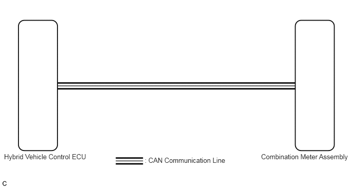
PROCEDURE
Check if CAN communication DTCs are output (See page Power Source / Network>NETWORKING>CAN COMMUNICATION SYSTEM>DIAGNOSIS SYSTEM).
- Result:
Result Proceed to DTCs are not output. A DTCs are output. B
A
B
(See pagePower Source / Network>NETWORKING>CAN COMMUNICATION SYSTEM>HOW TO PROCEED WITH TROUBLESHOOTING)
Connect the intelligent tester to the DLC3.
Turn the power switch on (IG).
Turn the intelligent tester on.
Enter the following menus: Body / Combination Meter / Active Test.
Check the operation by referring to the table below.
| Tester Display | Test Part | Control Range | Diagnostic Note |
|---|---|---|---|
| HV System Indicator | HV system indicator | MIN, -50, 0, 100, 200, 300, 400, MAX | - |
- OK:
Hybrid system indicator indication is normal.
OK
NG
Connect the intelligent tester to the DLC3.
Turn the power switch on (IG).
Turn the intelligent tester on.
Enter the following menus: Body / Combination Meter / Data List.
Check the values by referring to the table below.
| Tester Display | Measurement Item/Range | Normal Condition | Diagnostic Note |
|---|---|---|---|
| HV System Indicator | Hybrid system indicator value/ Min.: -512, Max.: 511 | -512 to 511 | - |
- OK:
Hybrid system indicator value displayed on the intelligent tester is almost the same as hybrid system indicator indication.
OK
NG
Replace the combination meter assembly with a new or a known good one (See page Vehicle Interior>METER / GAUGE / DISPLAY>COMBINATION METER>REMOVAL).
- OK:
The operation of the hybrid system indicator returns to normal.
OK
NG