Home › Vehicle Exterior › WINDOW / GLASS › POWER WINDOW CONTROL SYSTEM › 2011.12–2017.06
RM2170E _59 Vehicle Exterior _057045 WINDOW / GLASS _0278147 POWER WINDOW CONTROL SYSTEM J

WINDOW / GLASS  POWER WINDOW CONTROL SYSTEM  Front Passenger Side Power Window does not Operate with Front Passenger Side Power Window Switch  


DESCRIPTION

When the power switch is on (IG), the power window regulator motor assembly (for front passenger door) is operated by the power window regulator switch assembly (for front passenger door).

WIRING DIAGRAM
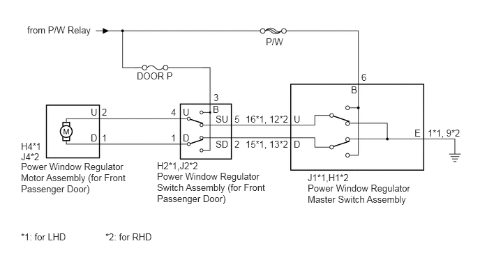
B301257E27
4.594,2.729 6.219,3.052 1.625,0.323 10 false Power Window Regulator Master Switch Assembly 2.344,2.552 4.021,3.042 1.677,0.49 10 false Power Window Regulator Switch Assembly (for Front Passenger Door) 0.313,2.406 1.948,2.896 1.635,0.49 10 false Power Window Regulator Motor Assembly (for Front Passenger Door) 4.594,2.573 5.302,2.719 0.708,0.146 10 false J1*1,H1*2 2.344,2.396 3.021,2.542 0.677,0.146 10 false H2*1,J2*2 0.313,2.26 0.625,2.406 0.313,0.146 10 false J4*2 0.313,2.104 0.667,2.25 0.354,0.146 10 false H4*1 6.188,1.906 6.302,2.052 0.115,0.146 10 false E 6.385,1.906 6.906,2.052 0.521,0.146 10 false 1*1, 9*2 5.24,1.26 5.354,1.406 0.115,0.146 10 false B 5.396,1.073 5.573,1.219 0.177,0.146 10 false 6 4.385,1.698 4.521,1.844 0.135,0.146 10 false U 2.729,1.594 2.865,1.74 0.135,0.146 10 false U 2.552,1.594 2.688,1.74 0.135,0.146 10 false 4 1.354,1.594 1.49,1.74 0.135,0.146 10 false U 1.521,1.594 1.656,1.74 0.135,0.146 10 false 2 3.219,1.698 3.438,1.844 0.219,0.146 10 false SU 3.177,1.552 3.292,1.698 0.115,0.146 10 false B 3.219,2.073 3.438,2.219 0.219,0.146 10 false SD 4.385,2.073 4.521,2.219 0.135,0.146 10 false D 2.729,1.979 2.865,2.125 0.135,0.146 10 false D 2.552,1.979 2.688,2.125 0.135,0.146 10 false 1 1.354,1.979 1.49,2.125 0.135,0.146 10 false D 1.521,1.979 1.656,2.125 0.135,0.146 10 false 1 3.188,1.375 3.323,1.521 0.135,0.146 10 false 3 3.5,1.698 3.635,1.844 0.135,0.146 10 false 5 3.667,1.698 4.333,1.844 0.667,0.146 10 false 16*1, 12*2 3.667,2.073 4.333,2.219 0.667,0.146 10 false 15*1, 13*2 3.5,2.073 3.635,2.219 0.135,0.146 10 false 2 3.969,0.542 4.292,0.688 0.323,0.146 10 false P/W 2.042,1.052 2.615,1.198 0.573,0.146 10 false DOOR P 0.406,0.365 1.406,0.51 1,0.146 10 false from P/W Relay 0.313,3.458 1.146,3.604 0.833,0.146 10 false *1: for LHD 1.573,3.458 2.427,3.604 0.854,0.146 10 false *2: for RHD

CAUTION / NOTICE / HINT

NOTICE:

Inspect the fuses for circuits related to this system before performing the following inspection procedure.


PROCEDURE

1.CHECK HARNESS AND CONNECTOR (POWER WINDOW REGULATOR SWITCH ASSEMBLY (FOR FRONT PASSENGER DOOR) - AUXILIARY BATTERY)
a.

Disconnect the power window regulator switch assembly (for front passenger door) connector.


b.

Measure the voltage according to the value(s) in the table below.

Standard Voltage:
for LHD
Tester Connection Condition Specified Condition
H2-3 (B) - Body ground Power switch on (IG) 11 to 14 V

for RHD
Tester Connection Condition Specified Condition
J2-3 (B) - Body ground Power switch on (IG) 11 to 14 V


OK

2.INSPECT POWER WINDOW REGULATOR SWITCH ASSEMBLY (FOR FRONT PASSENGER DOOR)

NG

REPAIR OR REPLACE HARNESS OR CONNECTOR

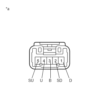
2.INSPECT POWER WINDOW REGULATOR SWITCH ASSEMBLY (FOR FRONT PASSENGER DOOR)
a.
B164433E19
0.199,0.223 0.382,0.365 0.184,0.142 10 *a 1.387,2.713 1.522,2.855 0.135,0.142 10 U 0.981,2.713 1.192,2.855 0.211,0.142 10 SU 2.401,2.713 2.536,2.855 0.135,0.142 10 D 1.696,2.713 1.831,2.855 0.135,0.142 10 B 1.971,2.713 2.184,2.855 0.213,0.142 10 SD 2.192,2.16 2.401,2.713 false 1.938,2.16 2.063,2.713 false 1.544,2.16 1.453,2.713 false 1.301,2.16 1.109,2.713 false 1.755,2.154 1.755,2.713 false

Remove the power window regulator switch assembly (for front passenger door) (See page Vehicle Exterior>WINDOW / GLASS>FRONT PASSENGER SIDE POWER WINDOW SWITCH>REMOVAL).


b.

Measure the resistance when the switch is operated according to the value(s) in the table below.

Standard Resistance:
Tester Connection Switch Condition Specified Condition
1 (D) - 2 (SD) UP Below 1 Ω
3 (B) - 4 (U) Below 1 Ω
1 (D) - 2 (SD) off Below 1 Ω
4 (U) - 5 (SU) Below 1 Ω
4 (U) - 5 (SU) DOWN Below 1 Ω
1 (D) - 3 (B) Below 1 Ω


Text in Illustration
*a Component without harness connected
(Power Window Regulator Switch Assembly (for Front Passenger Door))


OK

3.CHECK HARNESS AND CONNECTOR (POWER WINDOW REGULATOR SWITCH (FOR FRONT PASSENGER DOOR) - POWER WINDOW REGULATOR MOTOR)

NG

REPLACE POWER WINDOW REGULATOR SWITCH ASSEMBLY (FOR FRONT PASSENGER DOOR)

3.CHECK HARNESS AND CONNECTOR (POWER WINDOW REGULATOR SWITCH (FOR FRONT PASSENGER DOOR) - POWER WINDOW REGULATOR MOTOR)
a.

Disconnect the power window regulator motor assembly (for front passenger door) connector.


b.

Measure the resistance according to the value(s) in the table below.

Standard Resistance:
for LHD
Tester Connection Condition Specified Condition
H2-4 (U) - H4-2 (U) Always Below 1 Ω
H2-1 (D) - H4-1 (D) Always Below 1 Ω
H2-4 (U) - Body ground Always 10 kΩ or higher
H2-1 (D) - Body ground Always 10 kΩ or higher

for RHD
Tester Connection Condition Specified Condition
J2-4 (U) - J4-2 (U) Always Below 1 Ω
J2-1 (D) - J4-1 (D) Always Below 1 Ω
J2-4 (U) - Body ground Always 10 kΩ or higher
J2-1 (D) - Body ground Always 10 kΩ or higher


OK

4.INSPECT POWER WINDOW REGULATOR MASTER SWITCH ASSEMBLY

NG

REPAIR OR REPLACE HARNESS OR CONNECTOR

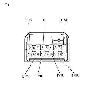
4.INSPECT POWER WINDOW REGULATOR MASTER SWITCH ASSEMBLY
a.
B298969E43
1.052,0.844 1.094,1.656 false 2.344,0.844 2.313,1.656 false 1.615,0.854 1.573,1.667 false 1.896,2.01 2.188,2.688 false 2.073,2.01 2.729,2.688 false 1.552,2 1.396,2.677 false 1.365,2 0.927,2.698 false 0.198,0.083 0.385,0.271 0.188,0.188 10 false *a 0.927,0.646 1.229,0.833 0.302,0.188 10 false E*B 2.083,2.688 2.406,2.875 0.323,0.188 10 false D*B 2.229,0.646 2.531,0.833 0.302,0.188 10 false E*A 1.573,0.646 1.729,0.833 0.156,0.188 10 false B 2.635,2.688 2.958,2.875 0.323,0.188 10 false U*B 0.792,2.708 1.083,2.896 0.292,0.188 10 false U*A 1.302,2.698 1.594,2.885 0.292,0.188 10 false D*A

Remove the power window regulator master switch assembly (See page Vehicle Exterior>WINDOW / GLASS>POWER WINDOW MASTER SWITCH>REMOVAL).


b.

Measure the resistance when the switch is operated according to the value(s) in the table below.

Standard Resistance:
for LHD
Tester Connection Switch Condition Specified Condition
6 (B) - 16 (U) UP Below 1 Ω
1 (E) - 15 (D) Below 1 Ω
1 (E) - 16 (U) off Below 1 Ω
1 (E) - 15 (D) Below 1 Ω
6 (B) - 15 (D) DOWN Below 1 Ω
1 (E) - 16 (U) Below 1 Ω

for RHD
Tester Connection Switch Condition Specified Condition
6 (B) - 12 (U) UP Below 1 Ω
9 (E) - 13 (D) Below 1 Ω
9 (E) - 12 (U) off Below 1 Ω
9 (E) - 13 (D) Below 1 Ω
6 (B) - 13 (D) DOWN Below 1 Ω
9 (E) - 12 (U) Below 1 Ω


Text in Illustration
*A for LHD
*B for RHD
*a Component without harness connected
(Power Window Regulator Master Switch Assembly)


OK

5.CHECK HARNESS AND CONNECTOR (POWER WINDOW REGULATOR MASTER SWITCH - POWER WINDOW REGULATOR SWITCH (FOR FRONT PASSENGER DOOR))

NG

REPLACE POWER WINDOW REGULATOR MASTER SWITCH ASSEMBLY

5.CHECK HARNESS AND CONNECTOR (POWER WINDOW REGULATOR MASTER SWITCH - POWER WINDOW REGULATOR SWITCH (FOR FRONT PASSENGER DOOR))
a.

Measure the resistance according to the value(s) in the table below.

Standard Resistance:
for LHD
Tester Connection Condition Specified Condition
J1-16 (U) - H2-5 (SU) Always Below 1 Ω
J1-15 (D) - H2-2 (SD) Always Below 1 Ω
J1-16 (U) - Body ground Always 10 kΩ or higher
J1-15 (D) - Body ground Always 10 kΩ or higher

for RHD
Tester Connection Condition Specified Condition
H1-12 (U) - J2-5 (SU) Always Below 1 Ω
H1-13 (D) - J2-2 (SD) Always Below 1 Ω
H1-12 (U) - Body ground Always 10 kΩ or higher
H1-13 (D) - Body ground Always 10 kΩ or higher


OK

REPLACE POWER WINDOW REGULATOR MOTOR ASSEMBLY (FOR FRONT PASSENGER DOOR)

NG

REPAIR OR REPLACE HARNESS OR CONNECTOR