RM2170E
_59
Vehicle Exterior
_057048
WIPER / WASHER
_0278172
WIPER AND WASHER SYSTEM
U
WIPER / WASHER WIPER AND WASHER SYSTEM TERMINALS OF ECU
CHECK HEADLIGHT CLEANER CONTROL RELAY

3.469,0.354 3.76,0.51
0.292,0.156
10
false
A44
a.
Disconnect the A44 headlight cleaner control relay connector.
b.
Measure the voltage and resistance according to the value(s) in the table below.
| Terminal No. (Symbol) | Wiring Color | Terminal Description | Condition | Specified Condition |
|---|---|---|---|---|
| A44-1 (HDLO) - A44-4 (E) | L - W-B | Low beam headlight signal | Light control switch in head position | Below 1 V |
| Light control switch off | 11 to 14 V | |||
| A44-2 (H) - A44-4 (E) | G - W-B | Headlight cleaner switch operation signal | Power switch on (IG) and headlight cleaner switch off | 11 to 14 V |
| Power switch on (IG), light control switch in head position and headlight cleaner switch on | Below 1 V | |||
| A44-3 (IG) - A44-4 (E) | V - W-B | Power switch on (IG) signal (Power source circuit) | Power switch off | Below 1 V |
| Power switch on (IG) | 11 to 14 V | |||
| A44-4 (E) - Body ground | W-B - Body ground | Body ground | Always | Below 1 Ω |
| A44-5 (FRWA) - A44-4 (E) | Y - W-B | Front washer switch signal | Power switch on (IG) and front washer switch off | 11 to 14 V |
| Power switch on (IG) and front washer switch on | Below 1 V | |||
| A44-6 (PB) - A44-4 (E) | R - W-B | Headlight cleaner motor drive output | Always | 11 to 14 V |
If the result is not as specified, there may be a malfunction in the wire harness.
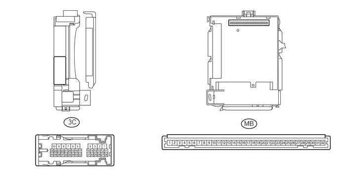
CHECK INSTRUMENT PANEL JUNCTION BLOCK ASSEMBLY AND MAIN BODY ECU (MULTIPLEX NETWORK BODY ECU)
5.146,2.531 5.479,2.76
0.333,0.229
10
false
MB
1.438,2.5 1.74,2.708
0.302,0.208
10
false
3C
a.
Measure the voltage and check for pulses according to the value(s) in the table below.
| Terminal No. (Symbol) | Wiring Color | Terminal Description | Condition | Specified Condition |
|---|---|---|---|---|
| 3C-18 (HRLY) - Body ground | V - Body ground | Headlight relay drive output | Light control switch in head position | Below 1 V |
| Light control switch not in head position | 11 to 14 V |
If the result is not as specified, the main body ECU (multiplex network body ECU) or instrument panel junction block assembly may have a malfunction.