WIPER / WASHER FRONT WIPER MOTOR INSTALLATION
PROCEDURE

 85110
1.INSTALL WINDSHIELD WIPER MOTOR ASSEMBLY
Install the windshield wiper motor assembly with the 3 bolts.
- Torque:
- 5.4 N*m (55 kgf*cm, 48 in.*lbf)
Connect the connector.
Turn the power switch on (IG).
Operate the wiper and stop the windshield wiper motor assembly at the automatic stop position.
Turn the power switch off.
Disconnect the connector.
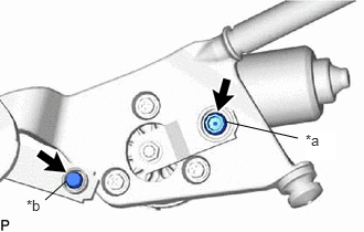
MP grease to the pivot of the windshield wiper motor assembly and windshield wiper link.
| *a | Windshield Wiper Crank Pivot |
| *b | Windshield Wiper Link Pivot |
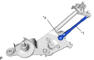
Connect the windshield wiper link No. 1 rod to the pivot of the windshield wiper motor assembly.
| *1 | Windshield Wiper Link No. 1 Rod |
| *a | Windshield Wiper Crank Pivot |
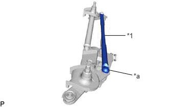
Connect the windshield wiper link No. 2 rod to the pivot of the wiper link assembly.
| *1 | Windshield Wiper Link No. 2 Rod |
| *a | Windshield Wiper Link Pivot |
2.INSTALL WINDSHIELD WIPER MOTOR AND LINK ASSEMBLY
Connect the connector .
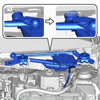
Engage the motor grommet as shown in the illustration.
| *1 | Motor Grommet |
- NOTICE:
-
Be careful not to damage the windshield when installing the windshield wiper motor and link assembly.
Install the windshield wiper motor and link assembly with the 2 bolts.
- Torque:
- 5.5 N*m (56 kgf*cm, 49 in.*lbf)
Engage the clamp.
55781E
3.INSTALL COWL TOP VENTILATOR LOUVER SUB-ASSEMBLY
Engage the 8 guides as shown in the illustration.
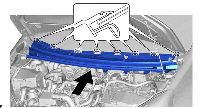
Engage the 3 guides and 5 claws to install the cowl top ventilator louver sub-assembly as shown in the illustration.
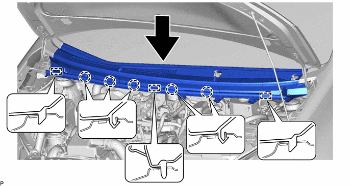
Connect the washer hose.
Install the 2 clips.
53867
4.INSTALL FRONT FENDER TO COWL SIDE SEAL LH
Clean the front fender to cowl side seal LH (if reusing the front fender to cowl side seal LH).
Remove the double-sided tape from the front fender to cowl side seal LH.
Wipe off any tape adhesive residue with cleaner.
Coat the installation surface on the front fender to cowl side seal LH with primer N-200.
- NOTICE:
- ·
Allow the primer to dry for 10 minutes or more.
·If 24 hours have elapsed since the primer was applied, reapply primer N-200.
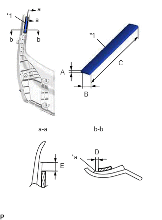
Apply new double-sided tape to the front fender to cowl side seal LH.
| *1 | Double-sided Tape |
| *a | Edge of Curved Surface |
| Item | Dimension |
|---|---|
| A | 0.5 mm (0.0197 in.) |
| B | 5.0 mm (0.197 in.) |
| C | 45.0 mm (1.77 in.) |
| D | 1.0 mm (0.0394 in.) |
| E | 2.0 mm (0.0787 in.) |
Clean the outside windshield moulding.
Remove the double-sided tape from the outside windshield moulding.
Wipe off any tape adhesive residue with cleaner
Coat the installation surface on the outside windshield moulding with primer N-200.
- NOTICE:
- ·
Allow the primer to dry for 10 minutes or more.
·If 24 hours have elapsed since the primer was applied, reapply primer N-200.
Install the front fender to cowl side seal LH.
Install the clip to the front fender to cowl side seal LH (if reusing the front fender to cowl side seal LH).
Engage the 2 guides and clip to install the front fender to cowl side seal LH as shown in the illustration.
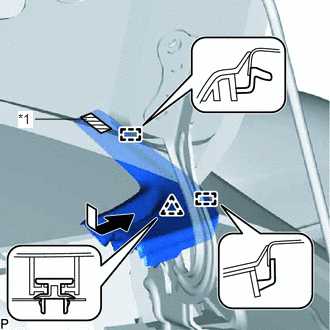
Remove the release paper from the double-sided tape on the front fender to cowl side seal LH.
| *1 | Double-sided Tape |
- HINT:
-
After removing the release paper, keep the exposed adhesive free from foreign matter.
Install the front fender to cowl side seal LH.
53866
5.INSTALL FRONT FENDER TO COWL SIDE SEAL RH
- HINT:
-
Use the same procedure as for the LH side.
6.INSTALL FRONT WIPER ARM AND BLADE ASSEMBLY LH
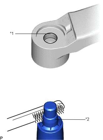
When reusing the front wiper arm and blade assembly LH:
Clean the wiper arm serrations.
| *1 | Wiper Arm Serration |
| *2 | Wiper Pivot Serration |
When reusing the windshield wiper link assembly:
Clean the wiper pivot serrations with a wire brush.
for LHD:
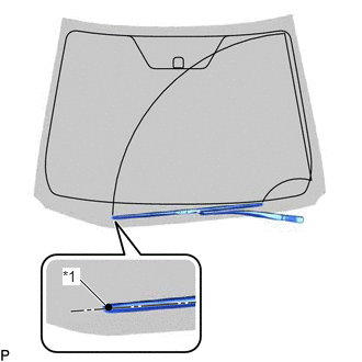
Install the front wiper arm and blade assembly LH with the nut to the position shown in the illustration.
- Torque:
- 26 N*m (265 kgf*cm, 19 ft.*lbf)
| *1 | Ceramic Dot |
- HINT:
-
Hold the wiper arm by hand while tightening the nut.
for RHD:
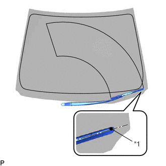
Install the front wiper arm and blade assembly LH with the nut to the position shown in the illustration
- Torque:
- 26 N*m (265 kgf*cm, 19 ft.*lbf)
| *1 | Ceramic Dot |
- HINT:
-
Hold the wiper arm by hand while tightening the nut.
7.INSTALL FRONT WIPER ARM AND BLADE ASSEMBLY RH
When reusing the front wiper arm and blade assembly RH:
Clean the wiper arm serrations.
| *1 | Wiper Arm Serration |
| *2 | Wiper Pivot Serration |
When reusing the windshield wiper link assembly:
Clean the wiper pivot serrations with a wire brush.
for LHD:
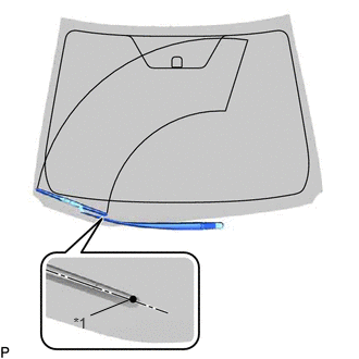
Install the front wiper arm and blade assembly RH with the nut to the position shown in the illustration.
- Torque:
- 26 N*m (265 kgf*cm, 19 ft.*lbf)
| *1 | Ceramic Dot |
- HINT:
-
Hold the wiper arm by hand while tightening the nut.
for RHD:
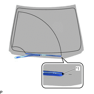
Install the front wiper arm and blade assembly RH with the nut to the position shown in the illustration.
- Torque:
- 26 N*m (265 kgf*cm, 19 ft.*lbf)
| *1 | Ceramic Dot |
- HINT:
-
Hold the wiper arm by hand while tightening the nut.
Turn the power switch on (IG).
Operate the front wiper while spraying washer fluid onto the windshield glass. Make sure that the front wiper functions properly and the wiper does not come into contact with the vehicle body.
Lift each wiper arm twice after the wipers stop and check the wiper set position.
Turn the power switch off.
85292B
8.INSTALL FRONT WIPER ARM HEAD CAP
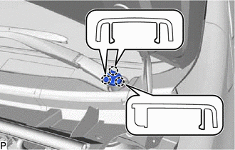
Engage the 3 claws to install the front wiper arm head cap.
- HINT:
-
Use the same procedure for the RH side and LH side.