Home › Vehicle Exterior › LIGHTING (EXT) › LIGHTING SYSTEM › 2011.12–2014.12
RM2170E _59 Vehicle Exterior _057049 LIGHTING (EXT) _0278196 LIGHTING SYSTEM J

LIGHTING (EXT)  LIGHTING SYSTEM  Back-up Light Circuit  


DESCRIPTION

The power management control ECU controls the back-up lights via the BKUP LP relay.

WIRING DIAGRAM
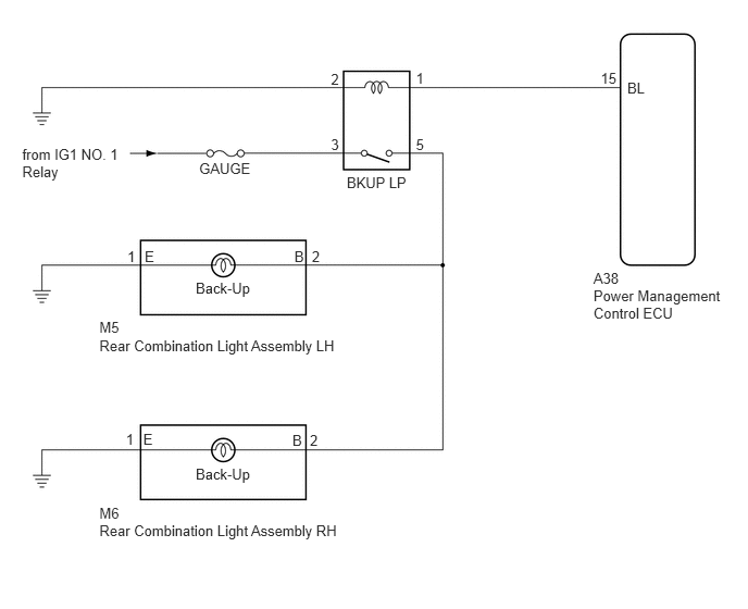
E233298E02
6.01,0.759 6.222,0.910 0.211,0.151 10 BL 5.755,0.672 5.928,0.823 0.173,0.151 10 15 3.985,0.672 4.082,0.823 0.097,0.151 10 1 3.171,0.673 3.268,0.824 0.097,0.151 10 2 3.985,1.302 4.082,1.453 0.097,0.151 10 5 3.171,1.302 3.268,1.453 0.097,0.151 10 3 5.686,2.58 5.951,2.730 0.266,0.151 10 A38 5.686,2.748 6.953,3.067 1.267,0.320 10 Power Management Control ECU 3.322,1.663 3.931,1.813 0.610,0.151 10 BKUP LP 2.988,2.378 3.085,2.528 0.097,0.151 10 2 1.22,2.378 1.317,2.528 0.097,0.151 10 1 0.952,3.057 1.226,3.208 0.274,0.151 10 M5 0.952,3.225 3.299,3.376 2.347,0.151 10 Rear Combination Light Assembly LH 0.952,4.834 1.177,4.985 0.225,0.151 10 M6 0.952,5.002 3.330,5.153 2.378,0.151 10 Rear Combination Light Assembly RH 1.908,1.527 2.433,1.677 0.525,0.151 10 GAUGE 0.213,1.394 1.240,1.745 1.027,0.351 10 from IG1 NO. 1 Relay 1.875,2.68 2.426,2.831 0.551,0.151 10 Back-Up 1.875,4.456 2.426,4.607 0.551,0.151 10 Back-Up 1.386,2.375 1.554,2.550 0.169,0.174 10 E 1.206,4.129 1.303,4.280 0.097,0.151 10 1 1.372,4.127 1.540,4.301 0.169,0.174 10 E 2.82,2.378 2.956,2.546 0.136,0.169 10 B 2.969,4.134 3.066,4.284 0.097,0.151 10 2 2.801,4.134 2.937,4.302 0.136,0.169 10 B

CAUTION / NOTICE / HINT

NOTICE:

Inspect the fuses and bulbs for circuits related to this system before performing the following inspection procedure.


PROCEDURE

1.CHECK DTC OUTPUT (HYBRID CONTROL SYSTEM)
a.

Check for DTCs (See page Engine / Hybrid System>HYBRID / BATTERY CONTROL>HYBRID CONTROL SYSTEM>DTC CHECK / CLEAR).

OK:

Hybrid control system DTCs are not output.


OK

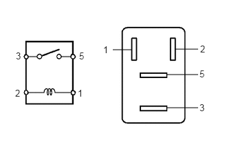
2.INSPECT BKUP LP RELAY

NG

2.INSPECT BKUP LP RELAY
a.
B426341E02
2.646,0.74 3,0.74 false 2.531,1.125 3,1.125 false 2.531,1.625 3,1.625 false 1.708,0.75 2,0.75 false 0.24,0.76 0.458,0.979 0.219,0.219 10 false 3 0.229,1.323 0.448,1.542 0.219,0.219 10 false 2 1.198,0.76 1.417,0.979 0.219,0.219 10 false 5 1.177,1.323 1.396,1.542 0.219,0.219 10 false 1 1.563,0.667 1.781,0.885 0.219,0.219 10 false 1 3.021,1.031 3.24,1.25 0.219,0.219 10 false 5 3.021,1.542 3.24,1.76 0.219,0.219 10 false 3 3.031,0.656 3.25,0.875 0.219,0.219 10 false 2

Remove the BKUP LP relay from the No. 2 engine room relay block and No. 2 junction block assembly.


b.

Measure the resistance according to the value(s) in the table below.

Standard Resistance:
Tester Connection Condition Specified Condition
3 - 5 Voltage is not applied between terminals 1 and 2 10 kΩ or higher
3 - 5 Voltage is applied between terminals 1 and 2 Below 1 Ω


OK

3.CHECK HARNESS AND CONNECTOR (BKUP LP RELAY - IG1 NO. 1 RELAY AND BODY GROUND)

NG

REPLACE BKUP LP RELAY

3.CHECK HARNESS AND CONNECTOR (BKUP LP RELAY - IG1 NO. 1 RELAY AND BODY GROUND)
a.

Measure the voltage according to the value(s) in the table below.

Standard Voltage:
Tester Connection Condition Specified Condition
Relay terminal 3 - Body ground Power switch on (IG) 11 to 14 V


b.

Measure the resistance according to the value(s) in the table below.

Standard Resistance:
Tester Connection Condition Specified Condition
Relay terminal 2 - Body ground Always Below 1 Ω


OK

4.CHECK HARNESS AND CONNECTOR (BKUP LP RELAY - BACK UP LIGHT LH AND BACK UP LIGHT RH)

NG

REPAIR OR REPLACE HARNESS OR CONNECTOR

4.CHECK HARNESS AND CONNECTOR (BKUP LP RELAY - BACK UP LIGHT LH AND BACK UP LIGHT RH)
a.

Disconnect the M5 rear combination light assembly LH connector.


b.

Disconnect the M6 rear combination light assembly RH connector.


c.

Measure the resistance according to the value(s) in the table below.

Standard Resistance:
Tester Connection Condition Specified Condition
Relay terminal 5 - M5-2 (B) Always Below 1 Ω
Relay terminal 5 - M6-2 (B) Always Below 1 Ω
Relay terminal 5 - Body ground Always 10 kΩ or higher


OK

5.CHECK HARNESS AND CONNECTOR (BKUP LP RELAY - POWER MANAGEMENT CONTROL ECU)

NG

REPAIR OR REPLACE HARNESS OR CONNECTOR

5.CHECK HARNESS AND CONNECTOR (BKUP LP RELAY - POWER MANAGEMENT CONTROL ECU)
a.

Disconnect the A38 power management control ECU connector.


b.

Measure the resistance according to the value(s) in the table below.

Standard Resistance:
Tester Connection Condition Specified Condition
Relay terminal 1 - A38-15 (BL) Always Below 1 Ω
Relay terminal 1 - Body ground Always 10 kΩ or higher


OK

NG

REPAIR OR REPLACE HARNESS OR CONNECTOR