P510 HYBRID TRANSMISSION / TRANSAXLE SHIFT LEVER POSITION SENSOR ADJUSTMENT
PROCEDURE

 1.SECURE VEHICLE
Fully apply the parking brake and chock a wheel.
- CAUTION:
- ·
Make sure to apply the parking brake and chock a wheel before performing this procedure.
·If the vehicle is not secure and the shift lever is moved to N, the vehicle may suddenly move, possibly resulting in an accident or serious injury.
89451A
2.INSPECT SHIFT LEVER POSITION SENSOR POSITION
Turn the power switch on (READY).
Move the shift lever to D and release the brake.
- NOTICE:
-
Be sure to apply the parking brake and lock the wheels with chocks to secure the vehicle.
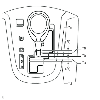
| *a | Gear Disengagement Point |
| *b | N Position |
| *c | R Position |
| *d | D Position |
Slowly move the shift lever to N and measure moving distance (A) of the shift lever from the original point to the gear disengagement point.
- NOTICE:
-
Be sure to move the shift lever slowly.
Move the shift lever to R and release the brake.
- NOTICE:
-
Be sure to apply the parking brake and lock the wheels with chocks to secure the vehicle.
Slowly move the shift lever to N and measure moving distance (B) of the shift lever from the original point to the vehicle disengagement point.
- NOTICE:
-
Be sure to move the shift lever slowly.
Check that moving distances (A) and (B) shown in the illustration are almost the same.
- HINT:
- ·
If moving distances (A) and (B) are almost the same, adjustment of the shift lever position is not necessary.
·If moving distance (A) is shorter than (B), perform adjustment of the shift lever position [*1].
·If moving distance (B) is shorter than (A), perform adjustment of the shift lever position [*2].
89451A
3.ADJUST SHIFT LEVER POSITION SENSOR POSITION
If moving distance (A) is shorter than (B). [*1]
- HINT:
-
If the shift lever is moved from R to N, the moving distance of the shift lever from the original point to the gear disengagement point becomes longer.
Move the shift lever to N.
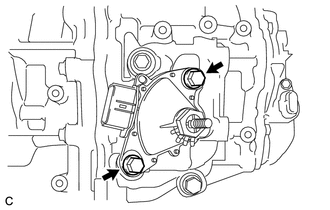
Loosen the 2 bolts.
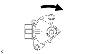
Slightly turn the shift lever position sensor clockwise.
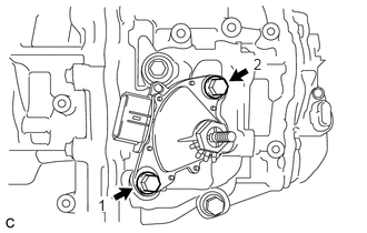
Tighten the 2 bolts in the order shown in the illustration.
- Torque:
- 13 N*m (133 kgf*cm, 10 ft.*lbf)
Recheck the shift lever position sensor.
If moving distance (B) is shorter than (A). [*2]
- HINT:
-
If the shift lever is moved from D to N, the moving distance of the shift lever from the original point to the gear disengagement point becomes longer.
Move the shift lever to N.
Loosen the 2 bolts.
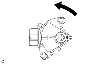
Slightly turn the shift lever position sensor counterclockwise.
Tighten the 2 bolts in the order shown in the illustration.
- Torque:
- 13 N*m (133 kgf*cm, 10 ft.*lbf)
Recheck the shift lever position sensor.