1NZ-FXE ENGINE MECHANICAL FRONT CRANKSHAFT OIL SEAL INSTALLATION
PROCEDURE

 15100C
1.INSTALL OIL PUMP SEAL
Apply MP grease to the lip of a new oil pump seal.
- NOTICE:
-
Keep the lip free from foreign matter.
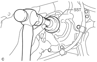
Using SST and a hammer, tap in the oil pump seal until its surface is flush with the front oil pump seal retainer edge.
- SST
- 09223-22010
- Tap in depth:
0 to 1.0 mm (0 to 0.00394 in.) from the edge of the timing chain cover.
- NOTICE:
- ·
Do not tap the oil pump seal at an angle.
·Wipe off extra grease from the crankshaft.
13407
2.INSTALL CRANKSHAFT DAMPER SUB-ASSEMBLY
Align the hole of the crankshaft damper sub-assembly with the straight pin, then install the crankshaft damper sub-assembly.
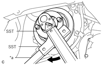
Using SST, hold the crankshaft damper sub-assembly in place and tighten the bolt.
| *a | Hold |

|
Turn |
- SST
- 09213-58012 (91111-50845)
09330-00021
- Torque:
- 128 N*m (1305 kgf*cm, 94 ft.*lbf)
- NOTICE:
-
When installing SST, be careful that the bolt which holds SST does not interfere with the timing chain cover.
12305
3.INSTALL ENGINE MOUNTING INSULATOR SUB-ASSEMBLY RH
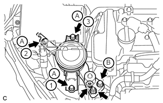
Temporarily install the engine mounting insulator sub-assembly RH with the 4 bolts and 2 nuts.
Tighten the 3 bolts (A) in the sequence shown in the illustration.
- Torque:
- 52 N*m (530 kgf*cm, 38 ft.*lbf)
Tighten the bolt (B) and 2 nuts.
- Torque:
- 52 N*m (530 kgf*cm, 38 ft.*lbf)
4.INSTALL NO. 2 ENGINE ROOM RELAY BLOCK AND NO. 2 JUNCTION BLOCK ASSEMBLY
Install the No. 2 engine room relay block and No. 2 junction block assembly with the 2 nuts and bolt.
- Torque:
- 5.4 N*m (55 kgf*cm, 48 in.*lbf)
5.INSPECT FOR OIL LEAK
6.INSTALL NO. 1 ENGINE UNDER COVER ASSEMBLY (Integrated Cover Type)
51441C
7.INSTALL ENGINE UNDER COVER RH (Separated Cover Type)
8.INSTALL FRONT WHEEL RH
- Torque:
- 103 N*m (1050 kgf*cm, 76 ft.*lbf)