RM2170E
_58
Vehicle Interior
_057037
METER / GAUGE / DISPLAY
_0320238
LIGHT CONTROL RHEOSTAT
G
METER / GAUGE / DISPLAY LIGHT CONTROL RHEOSTAT INSPECTION
PROCEDURE

 84119
1.INSPECT LIGHT CONTROL RHEOSTAT
a.
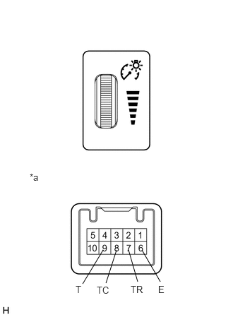
2.094,3.688 2.365,4.156
false
1.719,3.688 1.563,4.177
false
1.521,3.688 1.219,4.188
false
1.896,3.688 2.031,4.156
false
0.438,2.531 0.646,2.729
0.208,0.198
10
false
*a
1.427,4.198 1.656,4.375
0.229,0.177
10
false
TC
1.115,4.188 1.344,4.365
0.229,0.177
10
false
T
2.333,4.188 2.479,4.365
0.146,0.177
10
false
E
1.927,4.188 2.177,4.365
0.25,0.177
10
false
TR
Measure the resistance according to the value(s) in the table below.
- Standard Resistance:
Tester Connection Condition Specified Condition 6 (E) - 7 (TR) Light control rheostat is fully turned downwards (MIN.) Below 50 Ω 6 (E) - 7 (TR) Light control rheostat position is between MIN. and MAX. The value changes gradually (Between 0 to 12 kΩ 6 (E) - 7 (TR) Light control rheostat is fully turned upwards (MAX.) 8 to 12 kΩ 8 (TC) - 9 (T) Light control rheostat position is not fully turned upwards (Tail cancel switch is off) Below 50 Ω 8 (TC) - 9 (T) Light control rheostat is fully turned upwards (Tail cancel switch is on) 8 to 12 kΩ
| *a | Component without harness connected
(Light Control Rheostat) |
If the value is not as specified, replace the light control rheostat.