RM2170E
_58
Vehicle Interior
_057041
SEAT BELT
_0320196
SEAT BELT WARNING SYSTEM(w/ Occupant Classification System)
U
SEAT BELT SEAT BELT WARNING SYSTEM(w/ Occupant Classification System) TERMINALS OF ECU
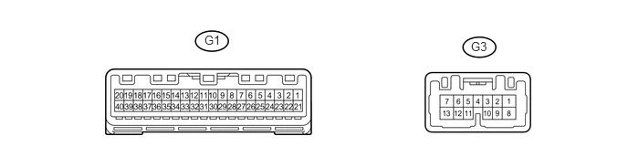
CHECK COMBINATION METER ASSEMBLY
2.333,0.375 2.625,0.594
0.292,0.219
10
false
G1
5.375,0.448 5.875,0.76
0.5,0.313
10
false
G3
a.
Disconnect the G1 combination meter assembly connector.
b.
Measure the resistance according to the value(s) in the table below.
- HINT:
-
Measure the values on the wire harness side with the connector disconnected.
| Tester Connection | Wiring Color | Terminal Description | Condition | Specified Condition |
|---|---|---|---|---|
| G1-20 (ET) - Body ground | BR - Body ground | Ground | Always | Below 1 Ω |
c.
Reconnect the G1 combination meter assembly connector.
d.
Measure the voltage according to the value(s) in the table below.
| Tester Connection | Wiring Color | Terminal Description | Condition | Specified Condition |
|---|---|---|---|---|
| G1-21 (IG+) - Body ground | B - Body ground | Ignition power supply
(IG signal) |
Power switch off | Below 1 V |
| G1-21 (IG+) - Body ground | B - Body ground | Ignition power supply
(IG signal) |
Power switch on (IG) | 11 to 14 V |
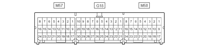
CHECK AIRBAG SENSOR ASSEMBLY
1.938,0.094 2.323,0.302
0.385,0.208
3.396,0.094 3.781,0.302
0.385,0.208
5,0.094 5.385,0.302
0.385,0.208
3.469,0.125 3.958,0.344
0.49,0.219
10
false
G18
2,0.115 2.396,0.344
0.396,0.229
10
false
M57
5.063,0.115 5.5,0.333
0.438,0.219
10
false
M58
| Terminal No. | Terminal Symbol | Destination |
|---|---|---|
| M57-10 | LBE+ | Front seat inner belt assembly LH |
| M57-18 | LBE- | Front seat inner belt assembly LH |
| M58-16 | FSR+ | Occupant detection ECU |
| M58-24 | FSR- | Occupant detection ECU |
CHECK OCCUPANT DETECTION ECU

4.323,0.135 4.615,0.313
0.292,0.177
10
false
O2
2.698,0.135 2.969,0.313
0.271,0.177
10
false
O1
a.
Measure the voltage according to the value(s) in the table below.
| Tester Connection | Wiring Color | Terminal Description | Condition | Specification |
|---|---|---|---|---|
| O2-1 (+B) - O2-3 (GND) | W - W-B | Auxiliary battery | Power switch off | 11 to 14 V |
| O2-2 (DIA) - O2-3 (GND) | GR - W-B | Diagnosis (DLC3) | Power switch on (IG), GTS not connected to DLC3 | Below 1 V |
| O2-3 (GND) - Body ground | W-B - Body ground | Ground | Always | Below 1 V |
| O2-4 (FSR-) - O2-3 (GND) | LG - W-B | Airbag sensor assembly communication line | Always | Below 1 V |
| O2-5 (BGND) - O2-3 (GND) | P - W-B | Front passenger buckle switch ground line | Always | Below 1 V |
| O2-6 (IG2) - O2-3 (GND) | B - W-B | Power source | Power switch on (IG) | 11 to 14 V |
| O2-7 (FSR+) - O2-4 (FSR-) | L - LG | Airbag sensor assembly communication line | Power switch on (IG) | Pulse generation |
| O2-8 (BSW) - O2-5 (BGND) | G - P | Front passenger buckle switch line | Always | Pulse generation |
| O1-2 (SVC3) - O1-6 (SGD3) | GR - W | Rear occupant classification sensor LH power supply line | Power switch on (IG) | 4.9 to 5.1 V |
| O1-1 (SVC1) - O1-5 (SGD1) | R - G | Front occupant classification sensor LH power supply line | Power switch on (IG) | 4.9 to 5.1 V |
| O1-4 (SIG3) - O1-6 (SGD3) | SB - W | Rear occupant classification sensor LH signal line | Power switch on (IG) | Pulse generation |
| O1-3 (SIG1) - O1-5 (SGD1) | P - G | Front occupant classification sensor LH signal line | Power switch on (IG) | Pulse generation |
| O1-5 (SGD1) - O2-3 (GND) | G - W-B | Front occupant classification sensor LH ground line | Always | Below 1 V |
| O1-6 (SGD3) - O2-3 (GND) | W - W-B | Rear occupant classification sensor LH ground line | Always | Below 1 V |